
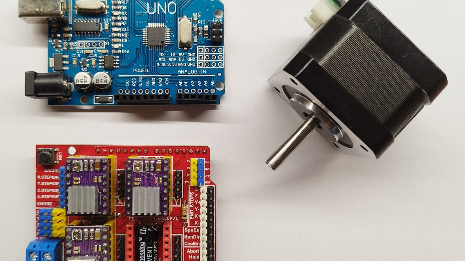
Set a DRV8825 carrier from the motor’s per-phase current rating, not from power-supply current. On Pololu’s carrier with 0.100 Ω sense resistors, the documented relationship is current limit = VREF × 2. A 1.0 A target therefore starts at 0.50 V. The formula is board-specific; verify the carrier and sense-resistor value before turning the trimmer.
Start with the motor winding, not the power supply
A bipolar stepper’s label or datasheet normally gives current per phase. That is the number the driver regulates. The bench supply shows input current after switching conversion, so it can be much lower than coil current when a high motor-supply voltage is stepped down into a low-voltage winding. Using the supply display to set the limit can therefore overdrive the motor.
- Find the motor’s rated current per phase.
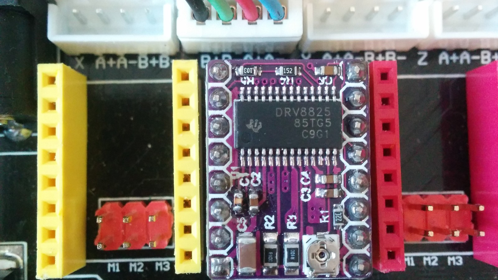
- Identify the exact carrier revision and its current-sense resistors.
- Choose a starting limit at or below the motor rating and below the board’s thermal capability.
- Power down before moving meter leads or changing motor wiring.
Convert the current target to VREF
For the documented Pololu DRV8825 carrier, the 0.100 Ω sense resistors produce this shortcut:
Current limit (A) = VREF (V) × 2
Rearranged, VREF = current limit ÷ 2. A 0.8 A limit maps to 0.40 V; 1.0 A maps to 0.50 V; and 1.2 A maps to 0.60 V. Measure between the carrier’s reference test point and logic ground with a high-impedance voltmeter. Use an insulated adjustment tool and avoid slipping across nearby pins.
Do not transfer that shortcut to every purple DRV8825 board. Clone carriers can use different sense resistors, layouts or markings. TI’s device-level relationship depends on VREF and the external sense resistance; the carrier vendor’s documentation is what turns it into a board-specific multiplier.
Verify coil current without confusing the 70% full-step reading
Pololu describes a second check: put the driver in full-step mode, stop the STEP input and measure in series with one motor coil. In that state both coils are energized at roughly 70% of the configured current limit. A 0.70 A coil reading therefore corresponds to a current limit near 1.0 A, not 0.70 A.
The reading also explains why a motor can feel warm even while stationary. Holding torque requires winding current. If firmware later changes current through a smart TMC driver, use its configured run current instead of applying a DRV8825 VREF rule. Klipper specifically cautions against adding hold_current by default because current transitions can disturb a motor and because reduced holding current may be unnecessary.

Read the symptom before turning the trimmer
Missed steps under acceleration: current may be too low, but acceleration, supply sag, mechanical drag or an undersized motor can produce the same symptom. Check those before adding current.
Driver shutdown after warming: current or cooling may be inadequate for the load. Pololu rates its carrier around 1.5 A per coil without a heat sink or forced air, despite the chip’s higher headline rating. More current requires real thermal management.
Motor too hot while idle: confirm the limit and firmware holding behavior. Do not infer coil current from the power brick.
Board dies when power is connected: investigate VMOT transients, wiring and decoupling instead of changing VREF. Pololu warns that long leads and low-ESR ceramic capacitors can create LC spikes above the DRV8825’s 45 V maximum, even from a 12 V supply. It recommends at least 47 µF of electrolytic capacitance close to VMOT and ground.
A repeatable stopping point
Use the lowest current that delivers reliable motion through the real acceleration and load range while keeping the driver and motor inside their documented thermal limits. Record the carrier revision, sense-resistor marking, VREF and firmware current settings. That short record prevents a later board swap from silently applying the wrong formula.
For deeper thermal diagnosis, see TVG’s motor-driver heat troubleshooting guide.


My experience with a similar setup showed a 15 percent variance in the expected current limit.