I²C pull-ups are not selected by choosing 4.7 kΩ from habit. SDA and SCL are open-drain lines: a device creates a low by sinking current, while a resistor and the bus capacitance determine how quickly the released line returns high. The usable resistor range therefore has two boundaries. Too much resistance makes the rising edge slow; too little asks a device to sink more current than it guarantees while maintaining a valid low voltage.
Define the bus before calculating
Record the pull-up rail, operating mode, devices, connectors, traces and cable. Estimate total bus capacitance Cb from pin-capacitance maxima, PCB and connector estimates, cable data, and probe loading. Calculate SDA and SCL separately. They can have different routing and loading, and SCL may be pulled low by more than the controller when clock stretching or multi-controller operation is supported.
Use the selected mode’s limits from NXP’s I²C specification:
- Standard-mode: up to 100 kbit/s, tr(max) = 1000 ns, nominal Cb(max) = 400 pF.
- Fast-mode: up to 400 kbit/s, tr(max) = 300 ns, nominal Cb(max) = 400 pF.
- Fast-mode Plus (Fm+): up to 1 Mbit/s, tr(max) = 120 ns, nominal Cb(max) = 550 pF.
These capacitance figures are limits, not targets. Meeting the resistor equation does not waive the mode’s other timing, fall-time, sink-current or compatibility requirements. A Fast-mode bus clocked at 100 kHz is not automatically a compliant Standard-mode bus.
Calculate both resistor limits
For the first-order RC rise of an I²C line, NXP and TI use the time between 30% and 70% of the pull-up voltage. That interval is 0.8473RpCb, giving the largest acceptable pull-up:
Rp(max) = tr(max) / (0.8473 Cb)
Use farads and seconds to obtain ohms. Do not substitute a scope’s 10%–90% rise-time measurement; set cursors at 30% and 70% of the relevant rail. Measure at the receiving end when wiring is long enough for location to matter.
The smallest acceptable resistor is set by the worst allowed pull-up voltage, the maximum low-level voltage and the guaranteed sink current:
Rp(min) = (VPU(max) − VOL(max)) / IOL
Take VOL(max) and IOL as a paired guarantee from the component datasheet. Do not use a typical pin current or the strongest device on the bus. The limiting value is the weakest guaranteed output among every device that may pull that line low, across the required voltage and temperature range. Check SCL and SDA independently.
Worked Fast-mode example
TI’s representative calculation uses a 3.3 V pull-up, 200 pF bus, 300 ns Fast-mode rise-time limit, 0.4 V maximum low level and 3 mA sink-current guarantee. The lower boundary is:
Rp(min) = (3.3 V − 0.4 V) / 0.003 A = 966.7 Ω
Worked example: use Fast-mode, tr(max) = 300 ns, and an estimated Cb = 200 pF:
Rp(max) ≈ 300 ns / (0.8473 × 200 pF) ≈ 1.77 kΩ.
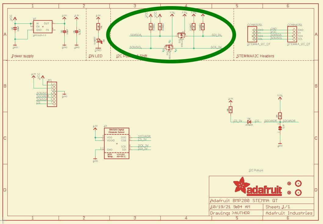
The electrical window is therefore approximately 967 Ω to 1.77 kΩ. A standard 1.0 kΩ or 1.5 kΩ part lies inside the calculated range, but tolerance matters: verify the resistor’s minimum value against the sink-current boundary and its maximum value against the rise-time boundary. Include capacitance uncertainty rather than treating 200 pF as exact.
Account for every pull-up already fitted
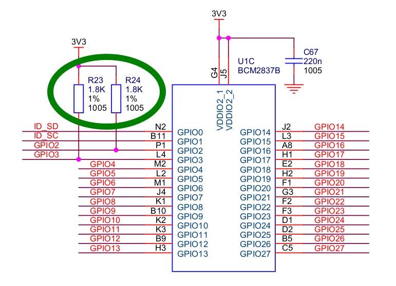
Breakout boards often include pull-ups. Connected pull-ups do not add in series; they form a lower equivalent resistance:
1 / Req = 1 / R1 + 1 / R2 + … + 1 / Rn
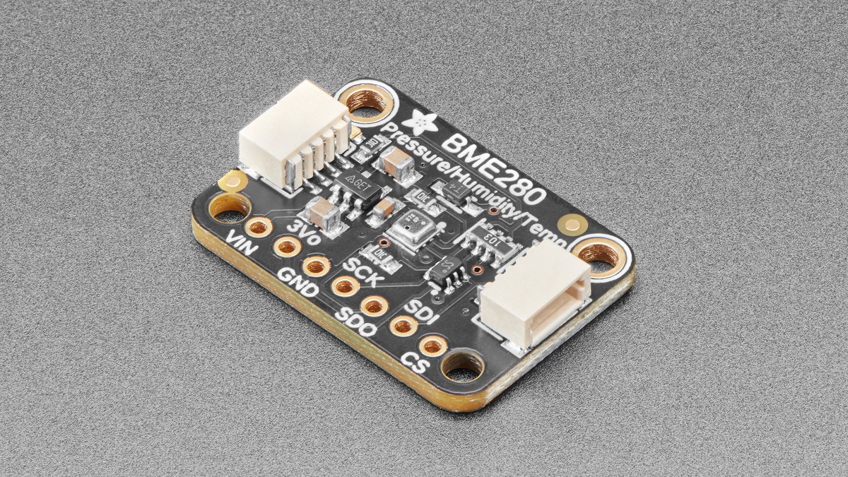
For equal resistors, Req = R / n. Four 4.7 kΩ pull-ups in parallel become 1.175 kΩ. That may improve rise time, but it also raises low-state current. Inventory controller-board and module resistors from schematics or measurements made with power removed; then compare the equivalent value with both calculated limits. Also confirm that no board pulls a line to an incompatible voltage.
Verify the assembled bus
- Fit a value inside both SDA and SCL windows, accounting for tolerance and all parallel resistors.
- Use an oscilloscope with a suitably low-capacitance probe. Measure 30%–70% rise time, high and low levels, ringing and edge shape at relevant nodes under worst-case voltage, loading and traffic.
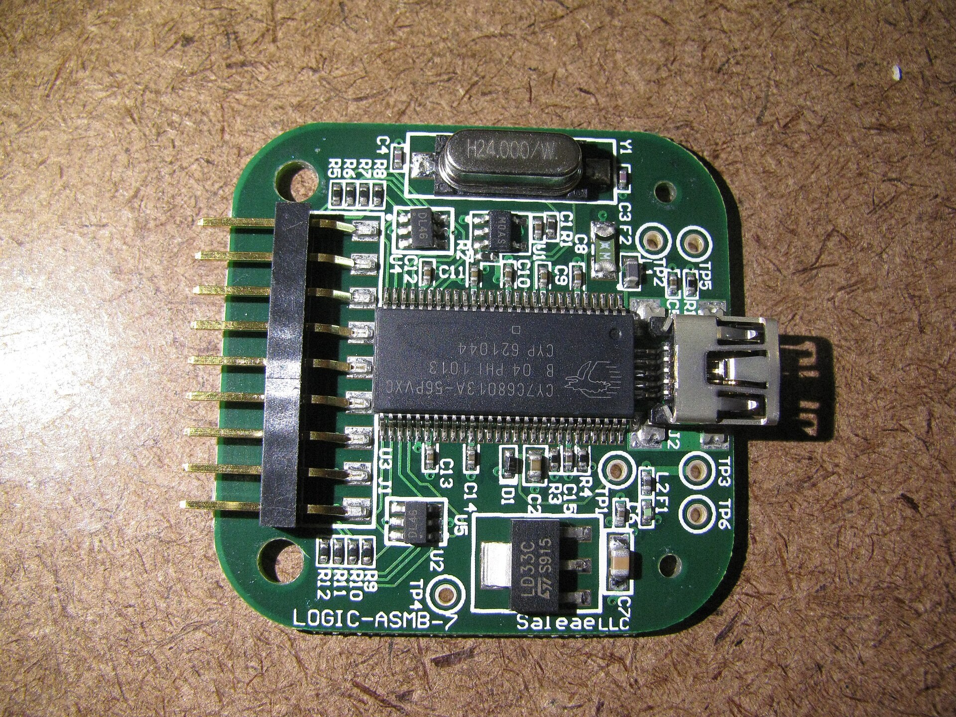
- Use a logic analyzer to inspect addresses, ACK/NACK states, repeated starts, clock stretching and protocol timing. Saleae’s I²C analyzer can expose transaction failures and offers glitch-filter controls, but digital decoding applies thresholds; a successful decode is not proof of analog rise-time or noise-margin compliance.
Reducing clock frequency can increase transaction timing margin, but it does not cure excessive sink current, an invalid voltage domain, crosstalk or ground movement. If the implementation is formally changed to Standard-mode, recalculate against Standard-mode requirements and confirm that every participant and timing parameter matches that mode.
When a resistor cannot solve it
If Rp(min) exceeds Rp(max), no resistor is valid. Reduce capacitance by shortening wiring or removing stubs, reduce the number of loads, use devices with appropriate Fm+ drive, lower the declared mode, or segment the bus with a suitable buffer.
Level translators and buffers are not transparent wires. Passive FET translators require pull-ups on both voltage domains and produce nonlinear transitions; evaluate each side’s capacitance, pull-up range and device thresholds. Buffers can isolate capacitance, but their offset low voltage, propagation delay, rise-time accelerators, direction rules, arbitration support and stuck-bus behavior differ. TI’s SCPA054 explains why some buffer combinations cannot recognize one another’s lows. Apply the translator or buffer datasheet limits before repeating waveform and protocol checks on every segment.