
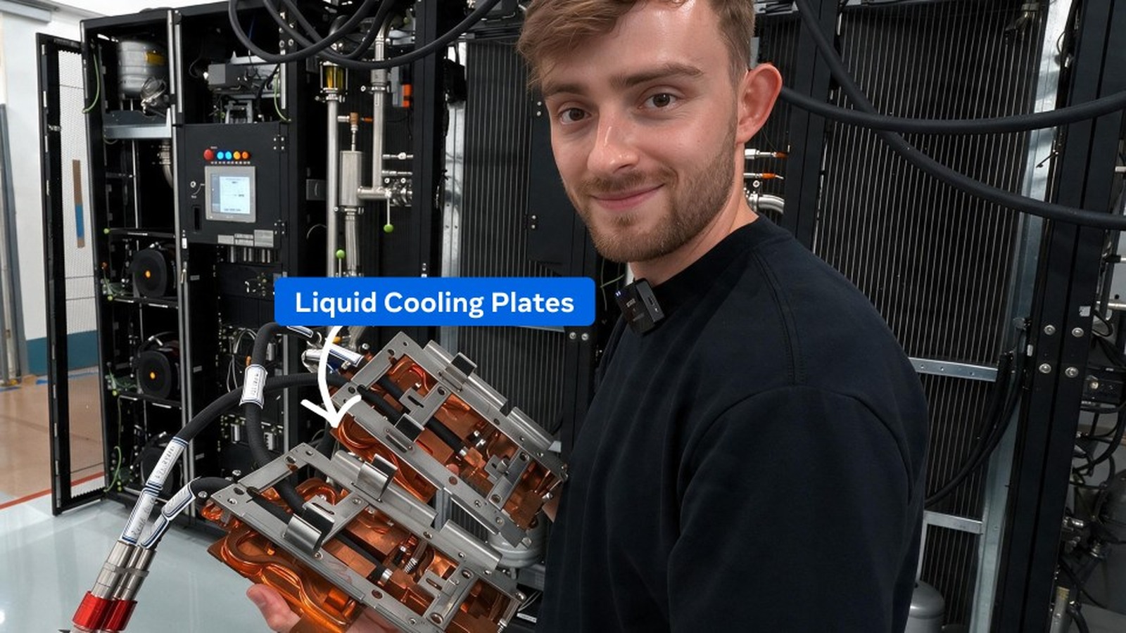
Meta has published a close look at the plumbing in one of its Texas AI facilities, showing how liquid moves heat away from high-power server components. The useful detail is not simply that the system is “closed loop.” It is where the rack coolant ends, where the facility loop begins and what the coolant distribution unit does between them.
What Meta disclosed
In an August 27 newsroom tour, Meta said the coolant in its newer AI-optimized facilities is a water-and-glycol mixture. Cold plates sit against heat-producing components, while pumps move coolant through server and rack manifolds. Meta says the liquid is recirculated in a sealed loop and requires little ongoing replacement.
That is a change from the air-cooled example Meta showed at an Iowa site, where a rack of 16 NVIDIA H100 GPUs relied on airflow and used water only upstream for warm-weather air cooling. The newer arrangement brings liquid directly to the hardware instead.
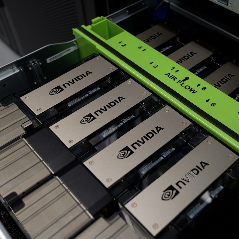
Follow the two-loop heat path
At the server, a cold plate conducts heat from a GPU or other high-power component into the rack coolant. Open Compute Project guidance describes this as a closed-loop cold-plate system: the plate is attached to the electronics, and liquid becomes the heat-transfer medium. ASHRAE likewise treats the cold plate as an integral server component rather than a room-level cooling accessory.
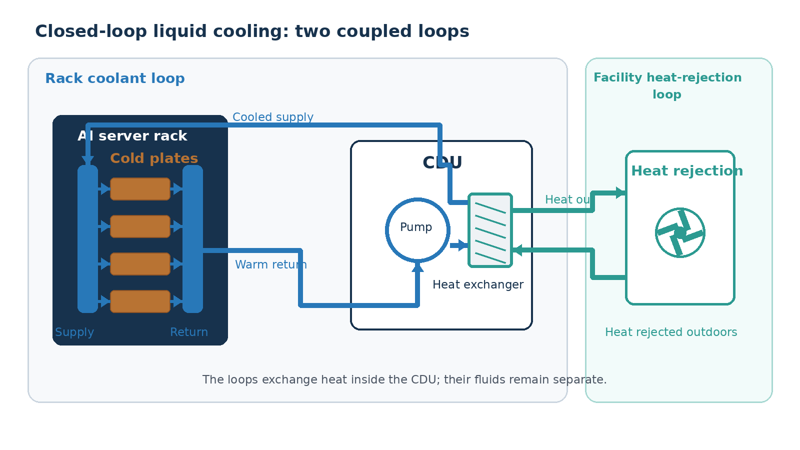
The warmed rack coolant returns to a coolant distribution unit, or CDU. Its pump maintains flow on the rack side, while its heat exchanger transfers energy to a separate facility-water loop. That second loop carries the heat toward chillers, dry coolers or another heat-rejection system selected for the site. Keeping the loops separate limits what reaches sensitive cold plates and lets facility engineers control pressure, chemistry and temperature on each side.
What “closed loop” does not prove
Closed-loop recirculation says something important about the rack circuit: coolant is not intended to be discarded after one pass. It does not, on its own, prove that an entire data center consumes no water. Facility heat rejection can be dry, evaporative or hybrid, and make-up water can still be needed elsewhere. Site climate, load, maintenance losses and the selected heat-rejection equipment determine the larger water balance.
The loop boundary also changes the maintenance plan. A leak, blocked cold plate or failed pump is a rack-side event; a chiller or dry-cooler problem sits on the facility side. Sensors at the CDU can reveal pressure, temperature and flow across that boundary, but the public tour did not provide alarm thresholds, redundancy design or site-level water figures. Those details are necessary before comparing facilities.
TVG Analysis
Meta’s tour is most useful as a component map, not as a single sustainability number. As rack power rises, cooling becomes a coupled server-and-building design problem: cold plates, quick disconnects, manifolds, CDUs, controls and facility equipment all have to agree on flow, temperature and failure response. The engineering question is no longer “air or liquid?” It is whether the complete heat path is serviceable, isolated and observable.
For a related look at how high-power compute changes system design, see TVG Report’s Hot Chips architecture coverage.

My office has a similar system that manages the heat flow differently. That specific setup requires a manual bypass when the load exceeds the standard parameters.