
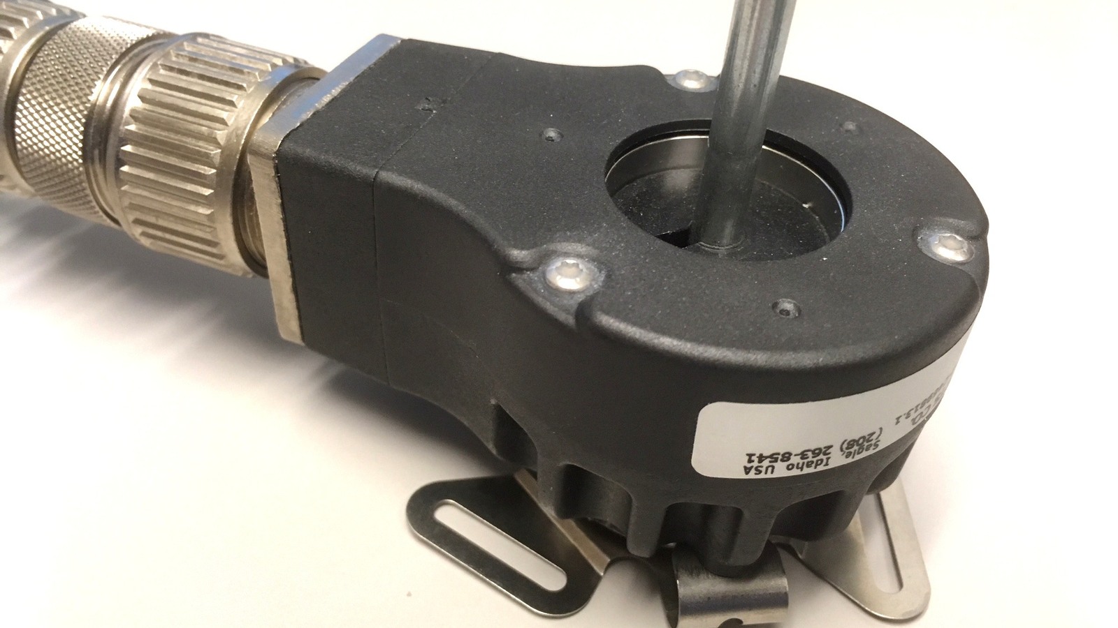
A rotary encoder that skips, reverses or adds counts is giving evidence about where its A/B sequence broke. Capture both channels and classify every transition before adding a longer debounce delay. The fault may begin at the contacts or optical pickup, but it can also come from weak pull-ups, cable interference, slow sampling, an overloaded interrupt path or a decoder that accepts impossible state changes.
Start with the four legal states
Quadrature uses two square waves shifted by 90 degrees. One forward sequence is 00 → 01 → 11 → 10 → 00; reverse rotation walks the same ring in the opposite direction. Only one bit changes at each legal step. A jump from 00 to 11 or from 01 to 10 changes both bits, so the decoder cannot know which intermediate state was missed.
Log the previous state, current state, timestamp and running count. Do not quietly convert an illegal transition into a direction guess. A rising total of illegal transitions is more useful than an apparently smooth count that hides errors.

Match counts to the decoding mode
Microchip’s AVR1600 describes one encoder cycle as four states. A decoder may count one selected edge per cycle (x1), both edges of one channel (x2), or every legal state change (x4). That means a device described as 24 pulses per revolution can produce a different software count depending on the manufacturer’s terminology and the decoder mode.
Write down the expected count explicitly: mechanical cycles per revolution × selected decode multiplier. AVR1600 uses a timer period of n × 4 − 1 for an encoder with n lines in its x4 hardware example. If the measured total is consistently one-half or one-quarter of expectation, check the chosen edge mode before treating it as random loss.
Capture at the MCU pins
Probe A, B and ground at the receiving pins, not only at the encoder. Turn the shaft slowly first, then at the speed that fails. Look for incomplete logic-high levels, ringing across the input threshold, narrow pulses and simultaneous-looking edges. A long cable can make a clean encoder output look poor at the controller; an internal pull-up that works on a breadboard can be too weak for cable capacitance and noise.
Keep separate counters for accepted forward steps, accepted reverse steps, repeated states and illegal two-bit jumps. Then compare those counters at slow and failing speeds. Repeated states without edges may simply reflect oversampling; illegal jumps that rise with speed indicate missed intermediate states. If the analyzer sees every legal transition while firmware does not, the mechanism and analog path have already passed a useful boundary test.
For a contacting encoder such as the Bourns PEC11R, bounce is part of the component specification. Filtering should reject chatter without discarding a legitimate next state. Fixed blocking delays are risky because they also impose a maximum accepted edge rate. A state-table decoder, input hysteresis where supported, suitable pull-ups and a bounded digital filter preserve more information.
Separate source, sampling and software
- Illegal states at the pin: inspect sensor alignment or contact condition, supply, grounding, shielding, pull-ups and edge shape.
- Legal states on the analyzer but missing in firmware: measure interrupt latency, disabled-interrupt windows, queue overruns and polling period.
- Correct edges but wrong direction: swap A/B in configuration or reverse the direction table—do not patch the final sign.
- Correct relative motion but drifting absolute position: use the encoder’s index channel when available and treat an unexpected index count as an error signal.
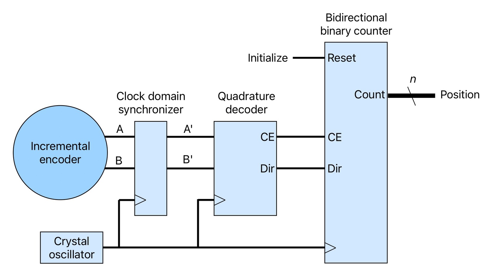
Microchip shows both event-system filtering and timer/counter decoding because dedicated hardware removes much of the timing variability of software polling. It still needs valid electrical signals and a count width large enough for the application. The durable fix is the one that makes the transition ledger clean at operating speed, not the one that merely makes a menu knob feel acceptable.
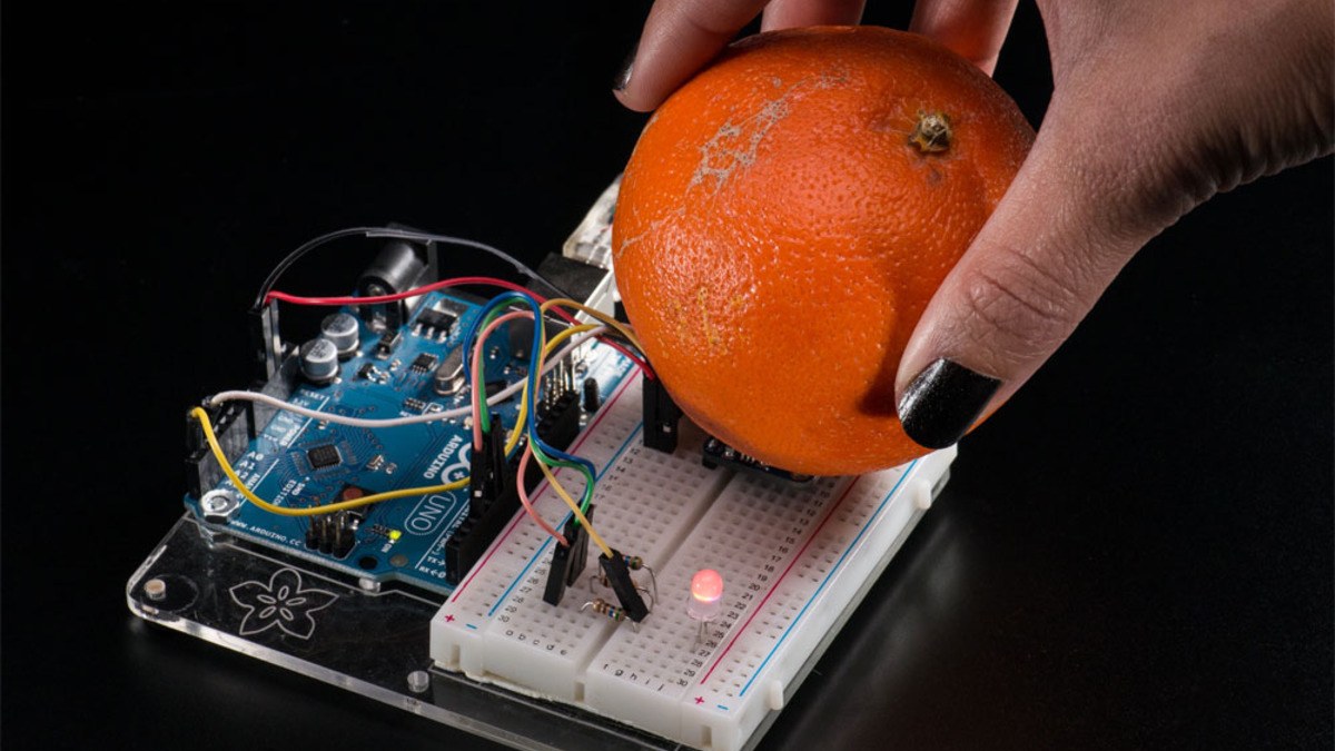

My previous setup experienced count loss only when the rotation speed exceeded a specific threshold.