
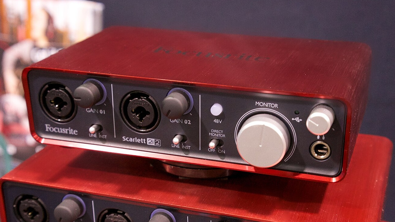
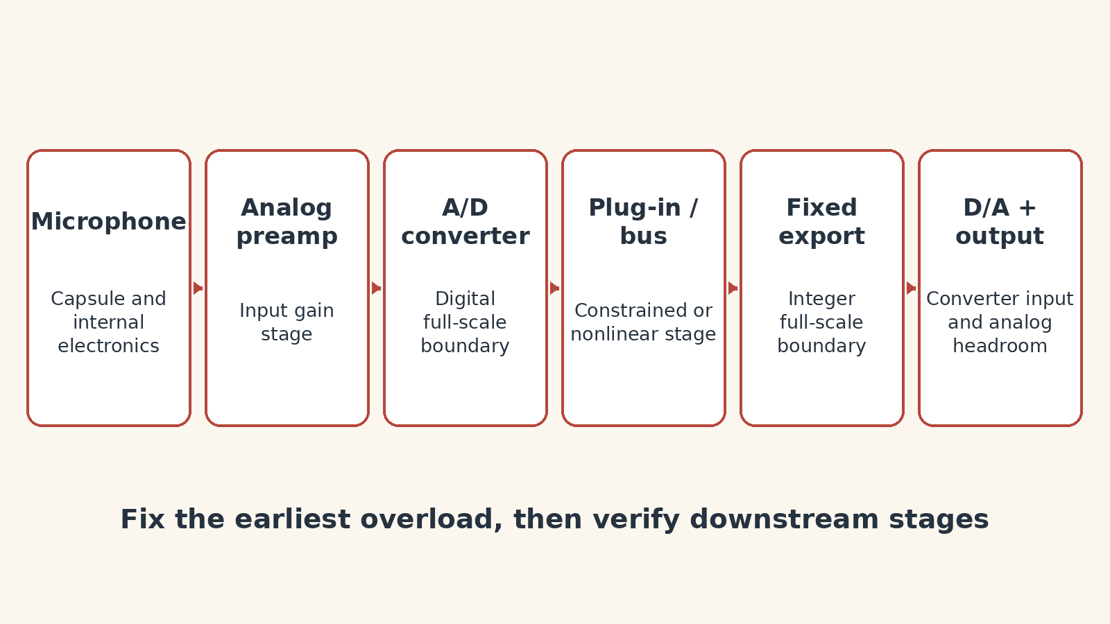
When a USB recording sounds distorted, lower the first stage that is actually overloaded—not the last meter that turns red. A microphone capsule, analog preamp, A/D converter, plug-in or fixed-point output can each fail at a different boundary. Reducing the DAW fader cannot repair clipping already recorded upstream.
Begin before the waveform
Ask whether the source itself or the microphone is distorting. A loud source can exceed a microphone capsule’s acoustic limit or overload active electronics before the interface receives the signal. Move the microphone, engage an appropriate pad if the hardware provides one, or use a microphone suited to the sound-pressure level. Do not assume every flat-topped waveform began in software.
Separate preamp overload from converter clipping
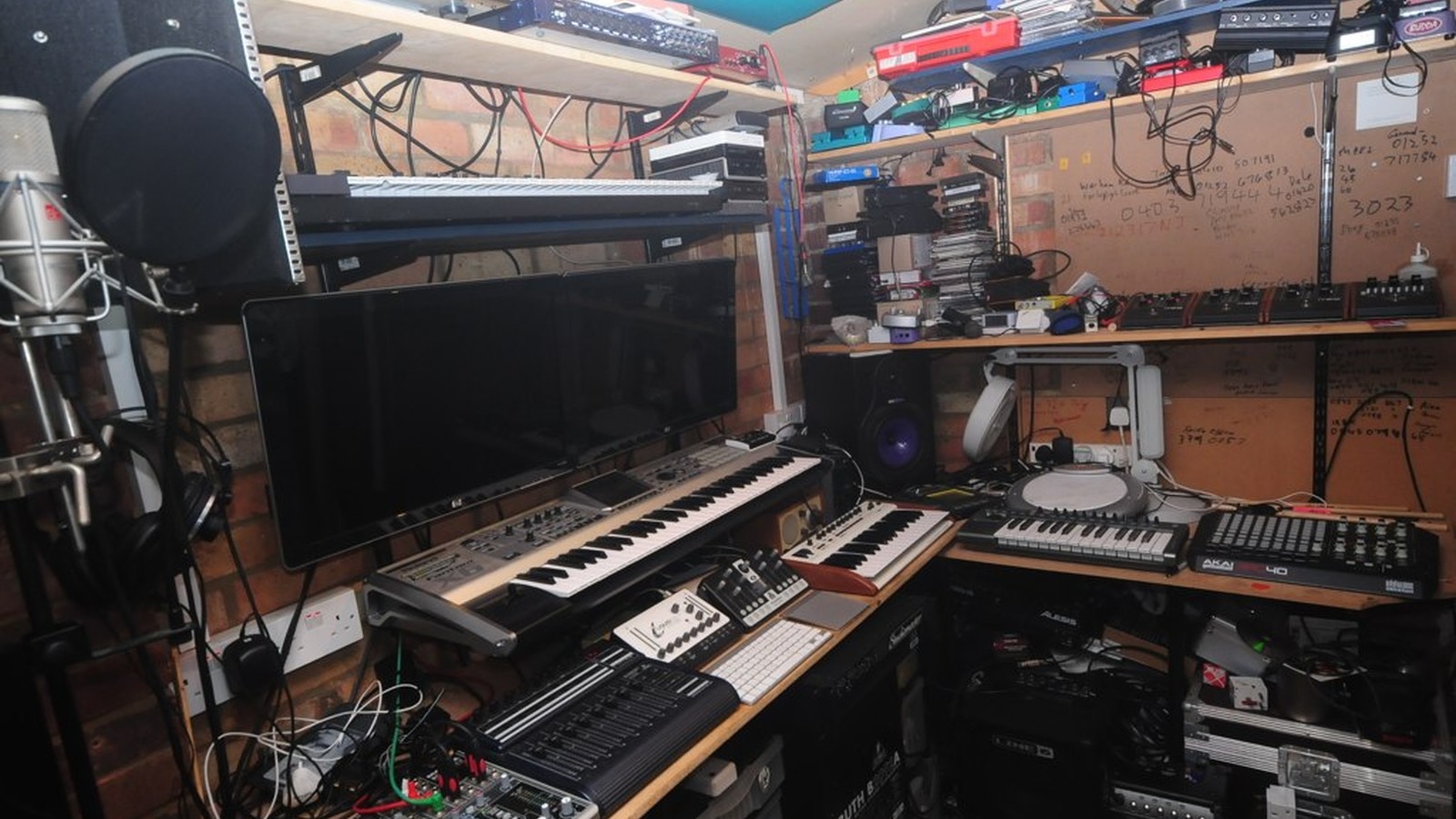
Focusrite’s gain guidance describes gain staging as maintaining healthy levels through each recording stage: too low can expose noise, while too high risks overload. The interface gain control sets the analog preamp level before conversion on typical microphone inputs. If the hardware input indicator clips, turn down that input gain first.
The A/D converter has a hard digital boundary. Once its input reaches full scale, samples cannot represent larger peaks. A DAW track fader is downstream, so pulling it down only reduces the level of an already clipped recording. Make a new test recording after changing input gain; an old clipped take will remain clipped.
Use meters to locate, not merely confirm, the problem
Audacity’s manual recommends monitoring recording level and checking the recorded waveform for clipping. Its clipping display can identify samples at the digital limit, but the picture alone cannot tell whether the microphone, preamp or converter overloaded first. Compare the hardware input indicator with the recorded waveform and listen to a short test at the loudest expected performance.
If the interface stays clean but distortion appears after processing, bypass plug-ins one at a time. A floating-point DAW bus can often carry values above nominal 0 dBFS internally, but individual plug-ins may model analog headroom, saturate intentionally or use a fixed internal limit. The relevant question is not simply whether a channel meter crossed zero; it is whether that specific stage changed the waveform nonlinearly.
Keep monitoring level separate from recording level. Turning down speakers or headphones changes what you hear, not what reaches the converter. Conversely, lowering a software monitor fader may make distortion less obvious while leaving the recorded samples unchanged. Compare the raw recording at a comfortable listening level before adjusting processing.
Check the final fixed boundary
The master path can overload a limiter, encoder, hardware output or fixed-point file conversion even when the recorded track is clean. Lower the level before that boundary, then render a short test and inspect it. True-peak overs can also appear during conversion or lossy encoding, so delivery specifications may require more margin than a sample-peak meter suggests.
Preserve one unprocessed test take while troubleshooting, and label it clearly with the interface gain position. If every adjustment is printed into a new file, it becomes difficult to distinguish an input-gain fix from a plug-in change or export-level change.
Shure’s gain-structure material frames the same systems principle: each electronic component has its own input and output limits. The useful troubleshooting order is source, microphone, preamp, converter, processing, bus and final output. Fix the earliest overload, then verify every downstream stage again.
A repeatable two-minute test
- Perform the loudest expected passage while watching the interface input indicator.
- Record ten seconds with plug-ins bypassed.
- Inspect and listen to that file before changing track or master faders.
- If clean, restore processing one stage at a time.
- Render the delivery format and check that exported file separately.
For field-video teams building a complete capture chain, TVG’s field audio kit guide covers microphone placement, monitoring and redundancy.

My setup occasionally shows distortion only when the input level exceeds eighty percent. That specific threshold changes depending on the cable quality I use.