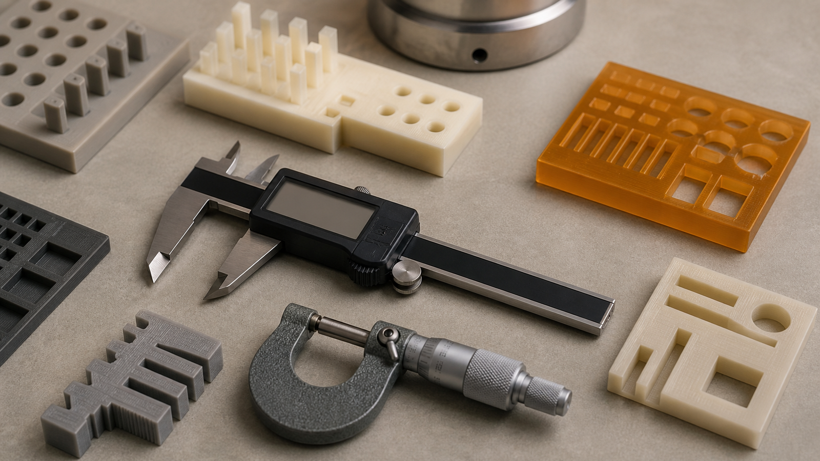
A digital caliper is the more useful first tool for most 3D-printing benches; a micrometer is the better specialist for small thickness and diameter checks. The instruments overlap, but they do not contact a part in the same way or tolerate the same measurement technique.
This is a buyer evaluation, not a hands-on comparison. TVG did not test a particular instrument. Accuracy depends on the tool’s condition, verification, operator technique, part geometry, and temperature.
Quick comparison
- Choose a caliper for outside dimensions, inside openings, depth, step measurements, and fast fit checks.
- Add a micrometer for filament diameter, thin walls, pins, shims, and controlled comparisons over a small range.
- Do not confuse resolution with accuracy. Extra digits do not prove the jaws are square or the frame is stable.
- Record the method so another builder measures the same faces with similar contact force.
Why the caliper belongs on the general bench
Calipers cover several measurement modes with one sliding tool. That makes them efficient for checking whether a printed bracket clears a shaft, whether a slot is wide enough, or how deep a recess actually printed. The tradeoff is a long jaw system that can tilt, flex, or bridge over a curved surface.
Use the outside jaws only on faces they can contact squarely. Inside jaws are useful for openings, but a small hole can be difficult because the jaw tips have geometry of their own. The depth rod needs a flat reference surface. If the part does not offer those conditions, a gauge pin, bore gauge, or purpose-built test coupon may provide stronger evidence.
Clean the jaws, close them gently, verify zero, and measure a known reference near the size of the part. Repeat the reading after rotating the part. A single value is weak evidence when layer seams, elephant’s foot, or rough surfaces can change where the jaws land.
Where a micrometer earns its place
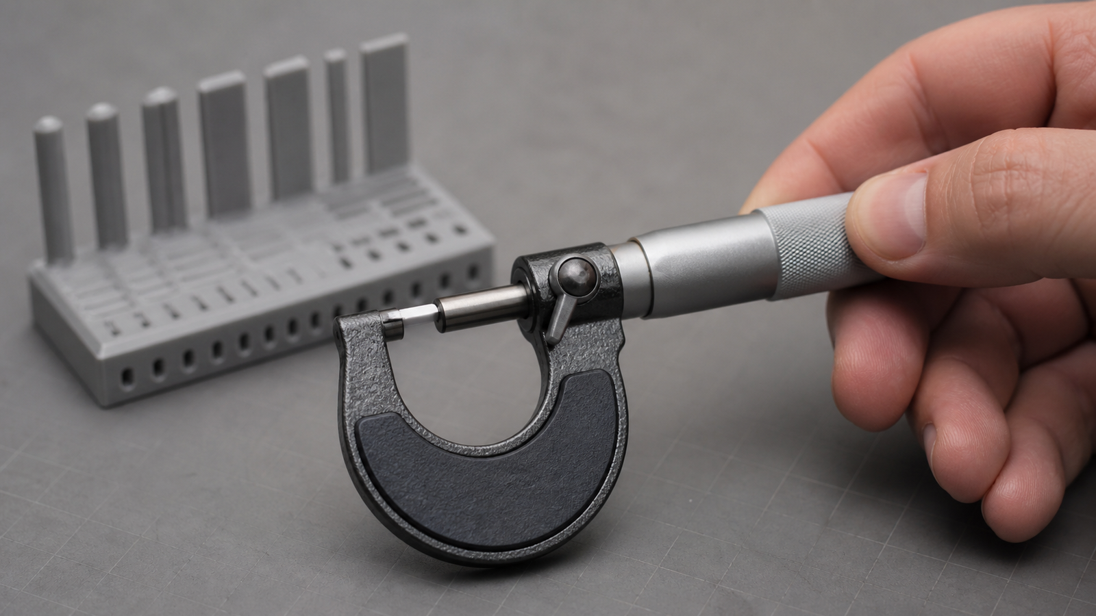
A micrometer uses a screw mechanism and a smaller measuring range. Many models include a ratchet or friction thimble to improve contact consistency. That controlled approach helps when comparing filament diameter or a thin printed wall at several points.
Choose the range before assuming one micrometer covers the bench. A 0–25 mm instrument answers different questions from a larger frame, and resolution still does not replace a verification standard. Let the tool and part reach the same room conditions for fine comparisons; warm hands and a recently printed polymer part can both shift a small reading.
It is not automatically the correct tool for a complex printed part. Flat anvils can contact only the high points of layer texture, and excessive force can compress soft polymer. Ball, blade, or other specialty anvils solve particular geometry problems, but they narrow the tool’s role and increase cost.
Measurement must support a decision
NIST’s SI length guidance provides the unit foundation, but a useful workshop record also states the instrument, measurement location, orientation, and repeat count. Prusa’s extrusion multiplier guidance is a reminder that dimensional results can reflect material flow as well as machine geometry.
Before changing slicer compensation, separate repeatable size error from first-layer deformation, backlash, loose mechanics, material shrinkage, and measurement variation. A drawing tolerance should describe the function that matters, not the number of decimal places on the tool.
TVG Take
Start with a decent caliper and a documented reference check. Add a micrometer when the project repeatedly asks a small-range thickness or diameter question that the caliper cannot answer consistently. The tool is only as useful as the measurement plan. TVG’s thermal-tool comparison applies the same principle: match evidence to the fault.