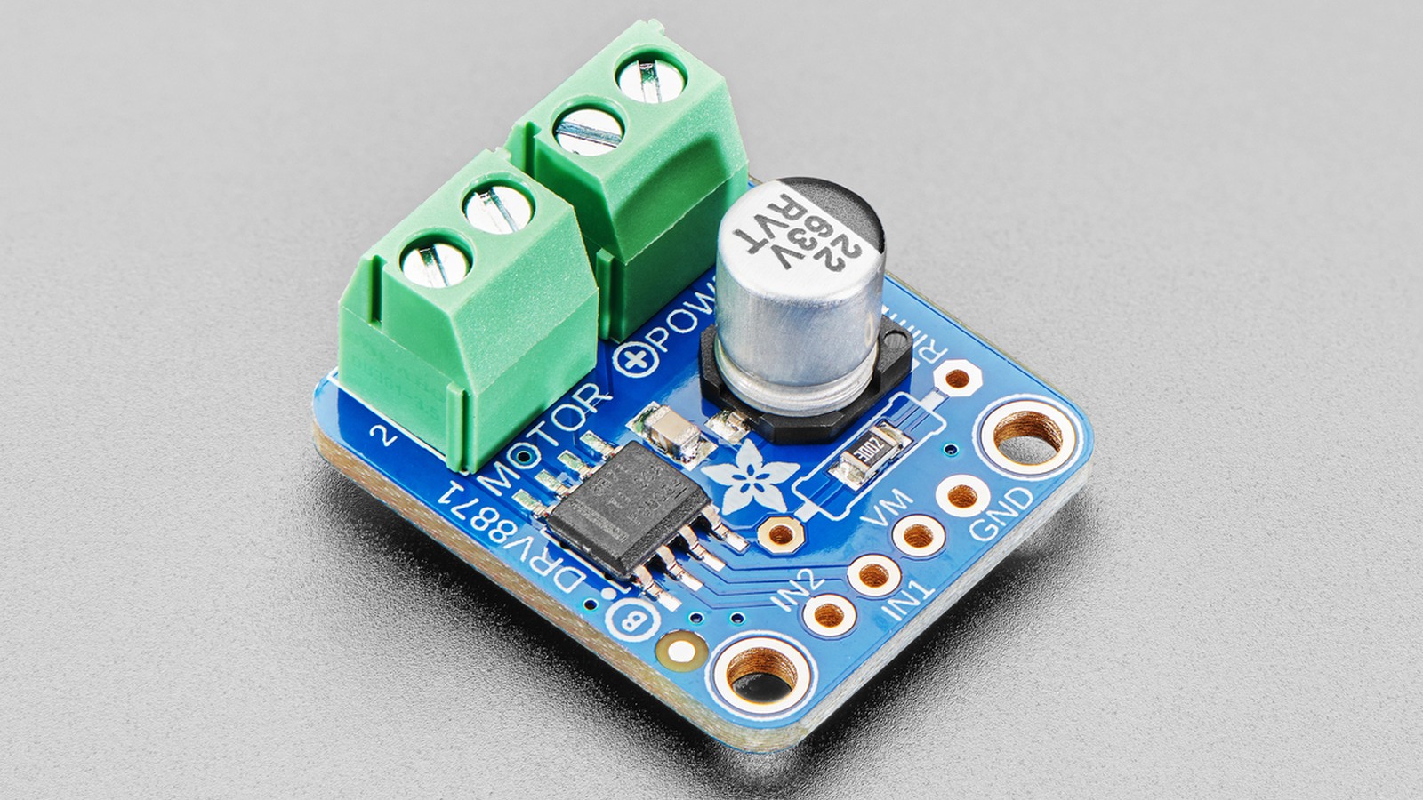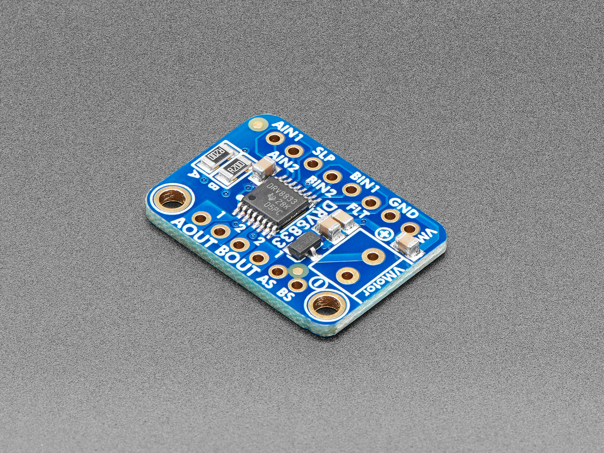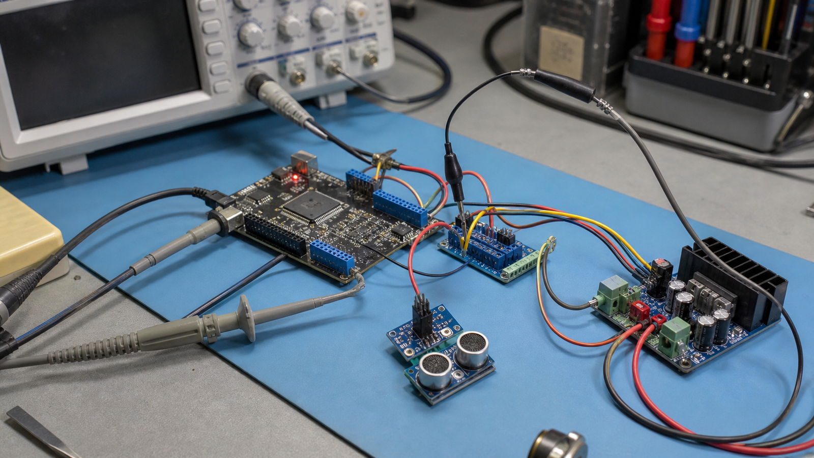
Erratic sensor readings are not automatically a code problem. A supply dip, poor connector, shared return path, long lead, or motor-switching event can disturb an otherwise valid reading. The useful question is whether the fault follows a measurable power event.
This guide is limited to low-voltage DC hobby and educational robots. It does not cover mains wiring, battery-pack or charger repair, or high-energy traction systems.
Work within a safe boundary
Disconnect the battery before moving connectors or changing components. Stay within the ratings of the circuit and test equipment, and do not open battery packs, probe mains wiring, or bypass protection. Stop if you see heat, swelling, smoke, odor, arcing, or damaged insulation. Because many bench oscilloscopes are earth-referenced, do not attach a ground clip to an unknown node.
Inspect before measuring
Note the battery state, robot load, sensor output, resets, temperature, and cable position before changing anything. With power removed, check for loose or reversed connectors, damaged insulation, strained leads, and wiring that can enter a wheel or actuator. If an error coincides with motor, servo, radio, or camera activity, treat that timing as a clue—not proof.
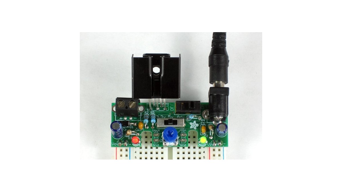
Measure at the sensor
- Check the documentation. Identify the exact sensor, controller, regulator, and motor driver. Find their allowed supply ranges, current limits, required capacitors, and grounding guidance.
- Check steady voltage. With a correctly rated multimeter, measure between supply and return at the sensor during safe operating states. A battery reading alone can miss loss in wiring or connectors.
- Compare repeatable loads. If the robot documentation allows a motor or other load to be disabled without bypassing an interlock, compare the same test with that load disabled and enabled. Power down before disconnecting anything.
- Compare timing. Log whether the sensor error, controller reset, rail change, connector movement, or temperature rise occurs first. A repeatable sequence is more useful than a single noisy sample.
A multimeter may miss a brief transient. An oscilloscope can reveal one, but poor probe placement, ground-lead inductance, limited bandwidth, and probe loading can also create misleading traces. Use the instrument manual and a rated probing method; otherwise stop at the multimeter and logged-event comparison. Save the readings with their measurement points and operating state. “Five volts” at the battery and “five volts” at the sensor during motor startup are not equivalent observations.
Do not guess at the fix
A separate rail, extra capacitor, or changed ground route may help, but none is universal. Use the measurements and component documentation to choose one change, then repeat the same load test. If the evidence remains ambiguous, restore the known configuration and seek an experienced electronics reviewer.