USB-C Power Delivery trigger boards are tempting because they can turn a common charger into a 9 V, 12 V, 15 V, or 20 V project supply. For maker labs, that can reduce old barrel-jack clutter. It can also create a new class of quiet power mistakes.
The USB-IF describes USB Power Delivery as a charging and power standard for higher-power USB systems. Adafruit’s USB-PD Hacks guide shows why makers are interested: a PD supply can replace bulky power bricks for projects when the negotiation and load are handled correctly.
Quick answer
Use a USB-C PD trigger board only after writing the project’s voltage, current, peak-load, fuse, connector, cable, and enclosure-label plan. A trigger board is not a universal power supply. It is a negotiation tool that still needs normal electrical design discipline.
Start with the load, not the charger
The first question is not whether the charger can advertise 65 W or 100 W. The first question is what the project actually draws at startup, steady state, stall, and failure. Motors, LED strips, heaters, radios, and SBCs behave differently under load.
A small robot accessory that draws little current at idle may pull much more during actuation. A camera rig may be stable until a display backlight and recorder start together. If the PD board negotiates 20 V but the downstream device expects 12 V, the clean connector becomes a damage path.
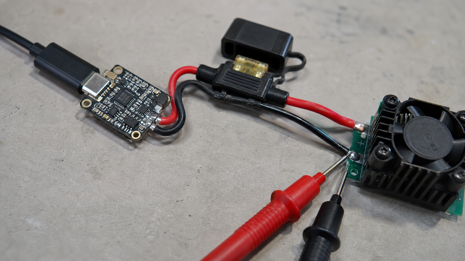
Maker-lab checklist
- Write the target voltage: do not rely on memory after the project is enclosed.
- Measure peak current: test startup and worst-case load, not only idle draw.
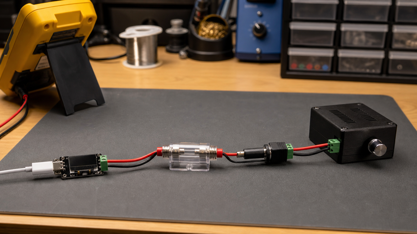
- Add protection: use fusing or current limiting where a fault could damage wiring.
- Respect cables: cheap or unknown USB-C cables may not behave like the charger rating suggests.
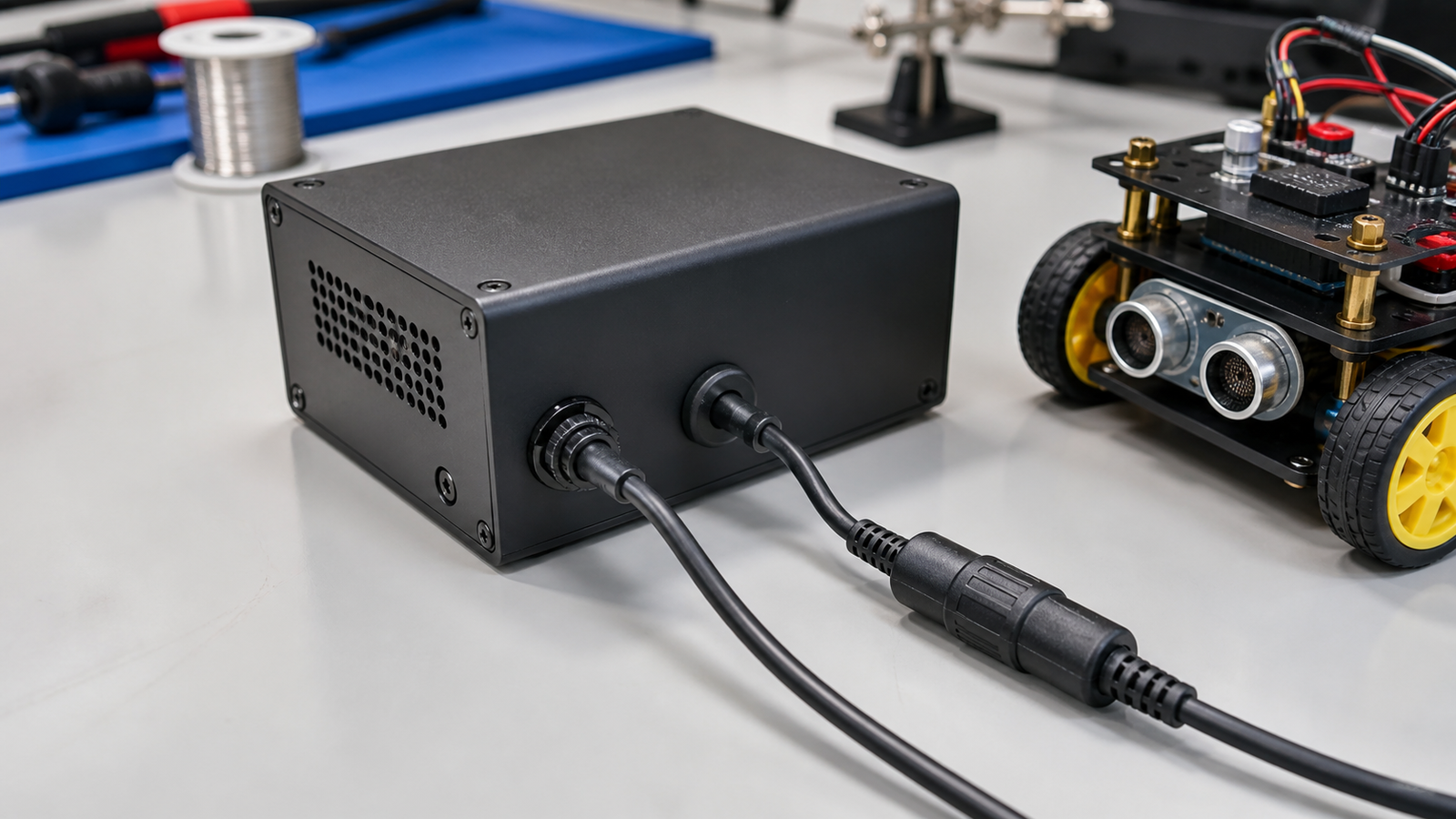
- Label the enclosure: future users need to know the negotiated voltage and polarity.
- Plan strain relief: the USB-C receptacle should not be the mechanical anchor.
Where this fits
USB-C PD is a strong option for benchtop tools, portable displays, small SBC projects, sensor kits, and low-to-medium power accessories. It is a weaker fit when the project has large motor surges, unknown loads, wet or rough environments, or users who may plug in random chargers without reading the label. TVG’s USB-C power bank vs V-mount guide covers the same theme for field media and robot rigs: power connectors are part of system design, not accessories.
TVG Take
USB-C PD trigger boards are useful because they make modern chargers accessible to maker projects. The risk is that the connector looks consumer-simple while the electrical consequences remain real. Treat every PD conversion as a power-budget exercise before it becomes a classroom tool or field accessory.