USB-C Power Delivery is tempting because it turns one connector into a flexible power source. For maker labs, that can reduce wall-wart clutter, standardize field kits, and make projects easier to transport. It can also hide mistakes until the robot browns out, the single-board computer reboots, or a cable quietly limits the whole build.
This is a guide, not a hands-on review of a specific charger or trigger board. TVG has not tested a new USB-C product for this article. The goal is to help robotics, STEM, and maker teams build a repeatable power checklist before relying on USB-C PD in a project.
Start with the source, not the connector
The USB Implementers Forum describes USB Power Delivery as part of USB’s shift from a limited data-and-power interface into a primary source of device power. In practice, that means the charger, cable, sink device, and any trigger or negotiation board must all agree on a power profile.
A USB-C plug by itself does not guarantee a useful voltage or current. A maker lab should record the charger rating, the advertised PD profiles, the cable rating, the expected project voltage, and the maximum load. If those numbers are not written down, the project is not ready to leave the bench.
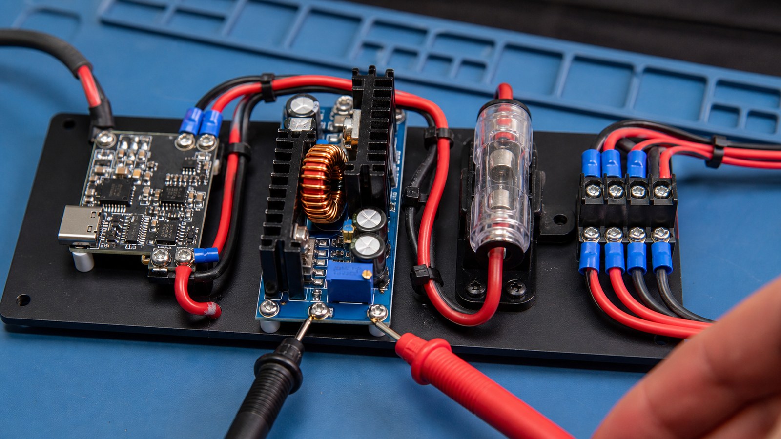
The maker-lab checklist
- Charger: choose a known charger with enough headroom for startup current, motors, radios, and attached displays.
- Cable: mark cables that have been verified for the required power level; do not assume every USB-C cable behaves the same.
- Negotiation: if a PD trigger board is used, document the selected voltage and verify it after power cycling.
- Conversion: step-down regulators, fuses, and reverse-polarity protection still matter after the PD stage.
- Brownout testing: test the worst case: motors starting, camera streaming, Wi-Fi active, and storage writing at the same time.
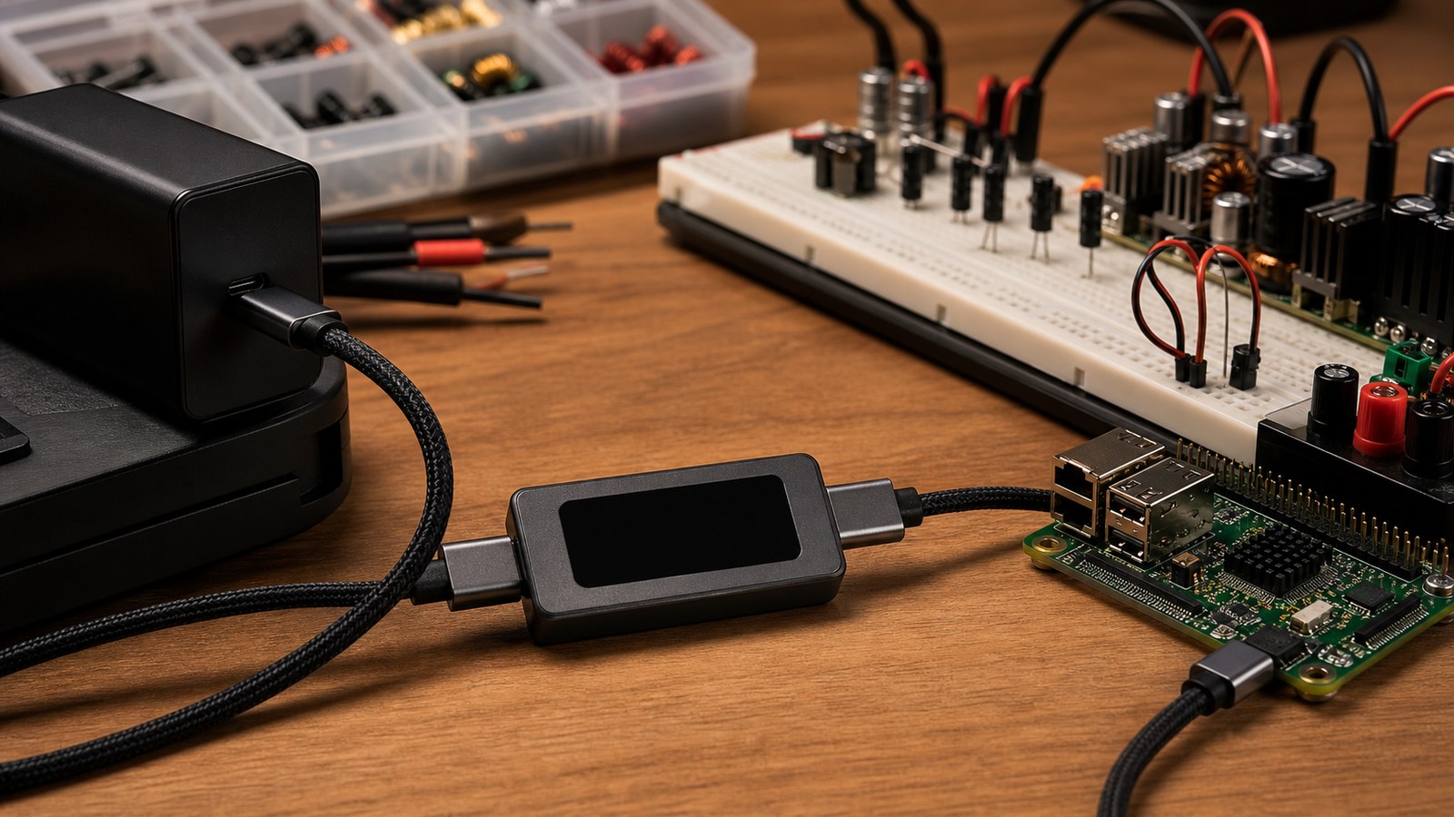
The Raspberry Pi documentation was blocked to this cron environment during source verification, but Raspberry Pi projects are a useful reminder: single-board computers can be sensitive to undervoltage and cable quality. Treat power as a system design problem, not an accessory purchase.
Where USB-C PD works well
USB-C PD is strongest for portable dashboards, bench instruments, sensor kits, classroom projects, field cameras, and low-to-moderate-power robot subsystems. It is weaker when teams expect it to replace a proper motor power system or when a project has high transient loads that were never measured.
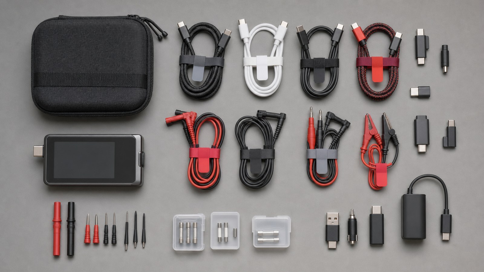
TVG Take
The best USB-C PD setup is boring: labeled cables, known chargers, protected rails, measured startup behavior, and one written fallback plan. If a project only works with one mystery charger and one lucky cable, it is not portable yet.
For related field documentation workflows, see TVG’s buyer evaluation on action cameras, 360 cameras, and phones for robot field documentation. Power discipline matters there too: the best camera angle is useless if the field kit cannot stay on through the test.
Document the failure case
A good power note includes what happens when the setup fails. Does the controller reboot when a motor starts? Does the display flicker when Wi-Fi connects? Does the voltage sag only with a long cable? Teams should capture those observations before replacing parts, because the failure pattern often points to the real constraint.
For STEM teams, this also turns power into a teaching asset. Students can measure voltage under load, compare cable behavior, and learn why connectors, wires, fuses, and regulators are part of the design rather than the cleanup phase.
Sources
- USB-IF: USB Charger / USB Power Delivery
- Raspberry Pi documentation: computers and power notes (403 to cron environment during verification)
- Arduino documentation: power pins