An intermittent sensor fault can look like a firmware bug when the real problem is a connector that shifts during motion. A harness may work on the bench, then fail after vibration, cable drag, servicing, or reassembly. A short physical check can help separate those problems before anyone changes code.
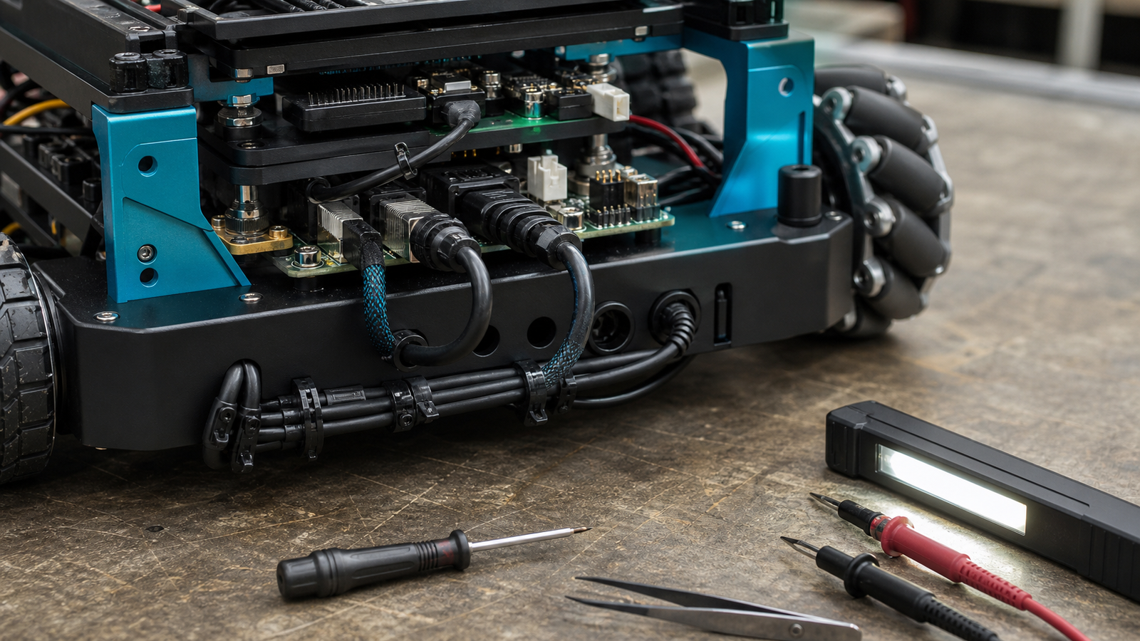
Start with power off
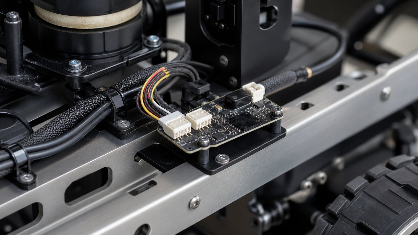
Disconnect power before touching the harness. Check that each housing is fully seated, its latch engages, and its orientation matches the socket. Give each wire a light individual pull to see whether a contact backs out; do not yank the bundle. Remove a connector by its housing, not its wires.
Follow the cable from the sensor to the controller. Look for damaged insulation, sharp bends behind a housing, cable weight hanging from a board connector, or a lead that a wheel, belt, arm, or cover can catch. The cable needs enough slack for normal motion and servicing, but not so much that it creates a moving loop or snag. Labels and a photo of known-good routing make later comparisons easier.
Connector families that look similar can still differ in latch, pitch, current rating and crimp system. For repairs, use the specified housing, contacts, wire size and tooling rather than forcing a near match.
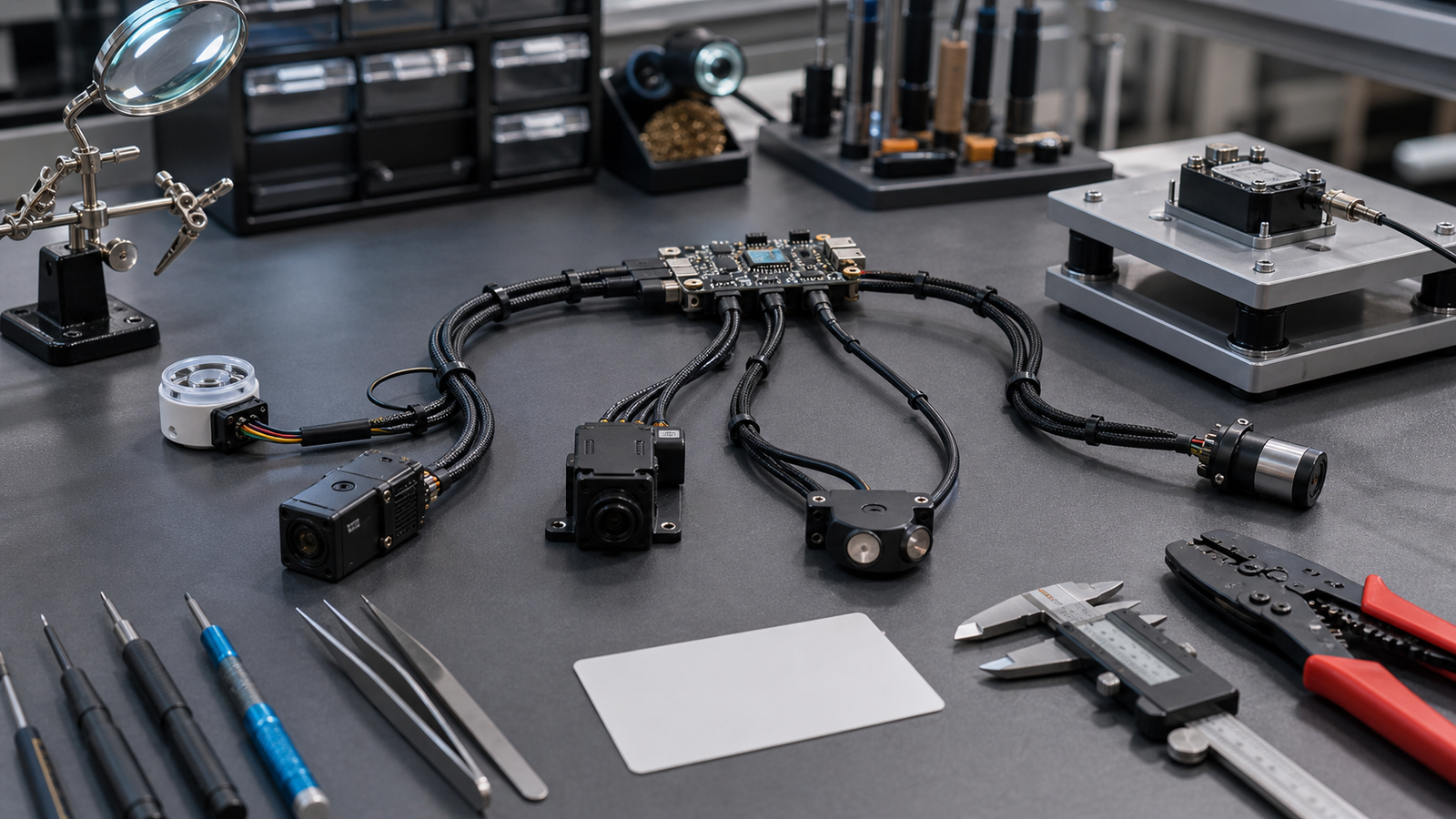
See whether motion triggers the fault
Restore power only after the inspection is complete. Reproduce the same robot movement while watching the sensor reading and any available error, reset, or supply-voltage logs. If the robot can be accessed safely, gently move one harness section at a time without reaching near moving parts, exposed conductors, or defeated guards.
If the dropout repeatedly follows one cable position, the harness deserves investigation. It does not yet prove which contact, crimp, conductor, or mating connector is faulty. Mechanical retention and electrical continuity are separate: a latched housing can contain a poor crimp, and a loose contact may conduct while stationary.
Use a known-good cable when practical
For a replaceable low-voltage lead, power down and fit a documented known-good cable with the same pinout and suitable electrical rating. Change nothing else, then repeat the same motion. If the fault disappears, reinstalling the suspect lead and seeing the fault return makes the comparison stronger. This identifies the original harness as a candidate cause, not the exact failure point.
Know when to stop
Stop testing if insulation is damaged, copper is exposed, a connector or wire becomes hot, arcing or odor appears, supply voltage leaves the device’s allowed range, or robot motion could trap the operator. Do not keep “wiggling” a cable after retention is lost. Repinning, crimp repair, and uncertain board-connector damage should go to someone with the correct documentation, tools, and experience.
If the harness remains stable, that still does not prove the firmware is wrong. Record the load, motion, cable position, timestamps, and observed errors so electrical and software debugging can continue from evidence rather than guesswork.