A robot sensor connector is a system, not just a housing. The contact, housing, conductor size, insulation diameter and crimp tool must belong to a validated combination. A contact can appear secure and still have damaged strands, an under-compressed conductor barrel or insulation trapped in the electrical crimp.
Start with the exact contact
Record the connector family and contact part number before selecting a die. Check the manufacturer’s application tooling specification for conductor gauge, insulation range, strip length, applicator or hand-tool number and locator setting. “JST-style” or “Molex-style” is not enough: similar-looking contacts may use different barrel geometry and inspection limits.
Strip only the specified length. The conductor should sit in the conductor barrel with the expected brush and bellmouth, while the insulation wings support the jacket without cutting it. Replace wire with nicked strands; do not hide strand loss inside the barrel.
Inspect what the manufacturer defines
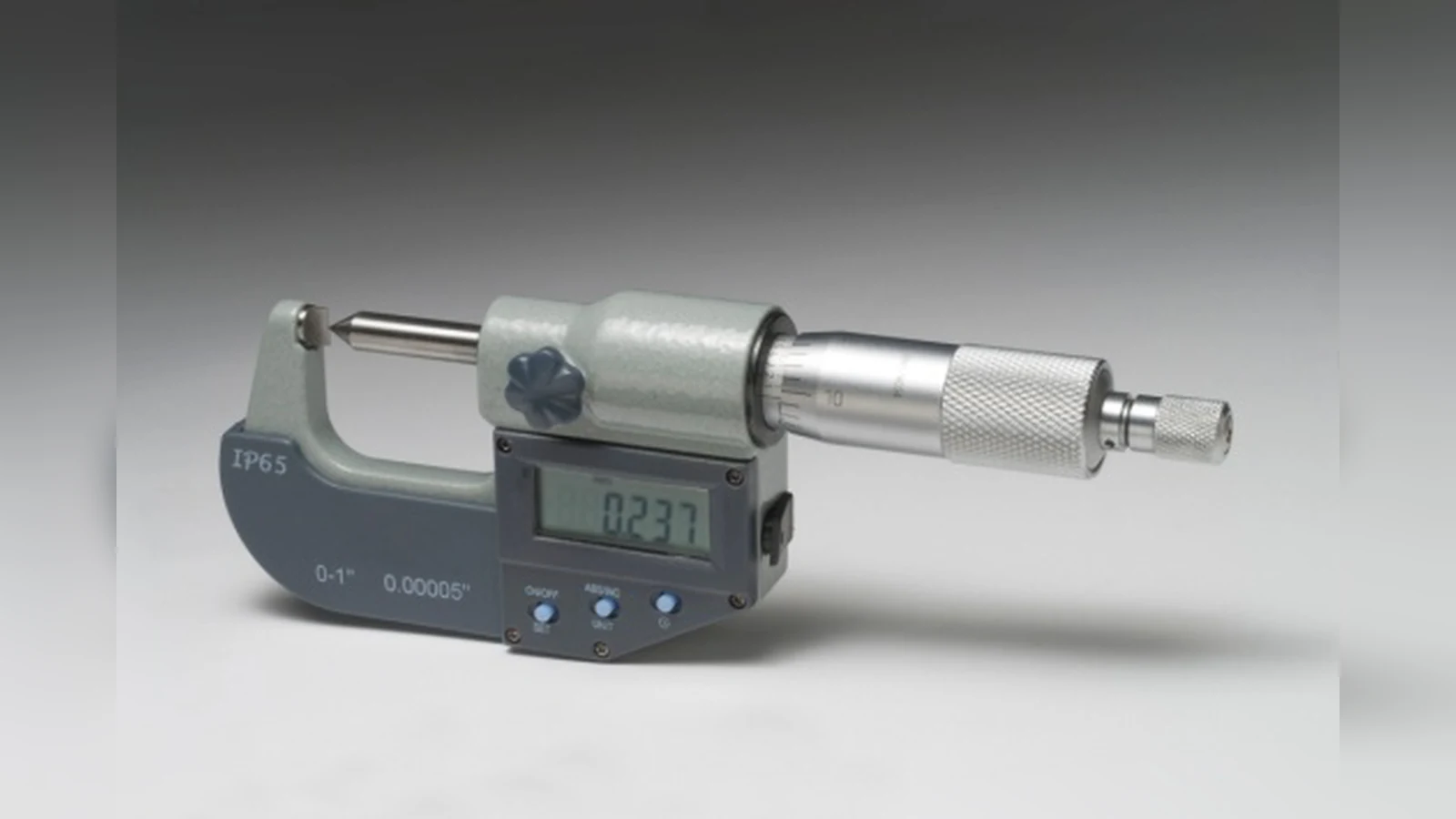
For production tooling, crimp height is a fast nondestructive process check, but the target belongs to that terminal-and-wire combination. Measure at the location and orientation shown by the manufacturer using a crimp-height micrometer. Also inspect conductor brush, bellmouth, cutoff tab, insulation position and contact deformation. A ratcheting tool completing its cycle does not prove that the wrong die, wire or contact produced a valid crimp.
Separate retention from strain relief
After insertion, verify the contact lance has locked into the housing with a controlled retention check. Then support the cable so robot motion, vibration and service pulls are carried by strain relief rather than the terminal interface. Secure the harness outside articulation and leave a deliberate service loop where motion requires it.
Use pull tests without inventing a threshold
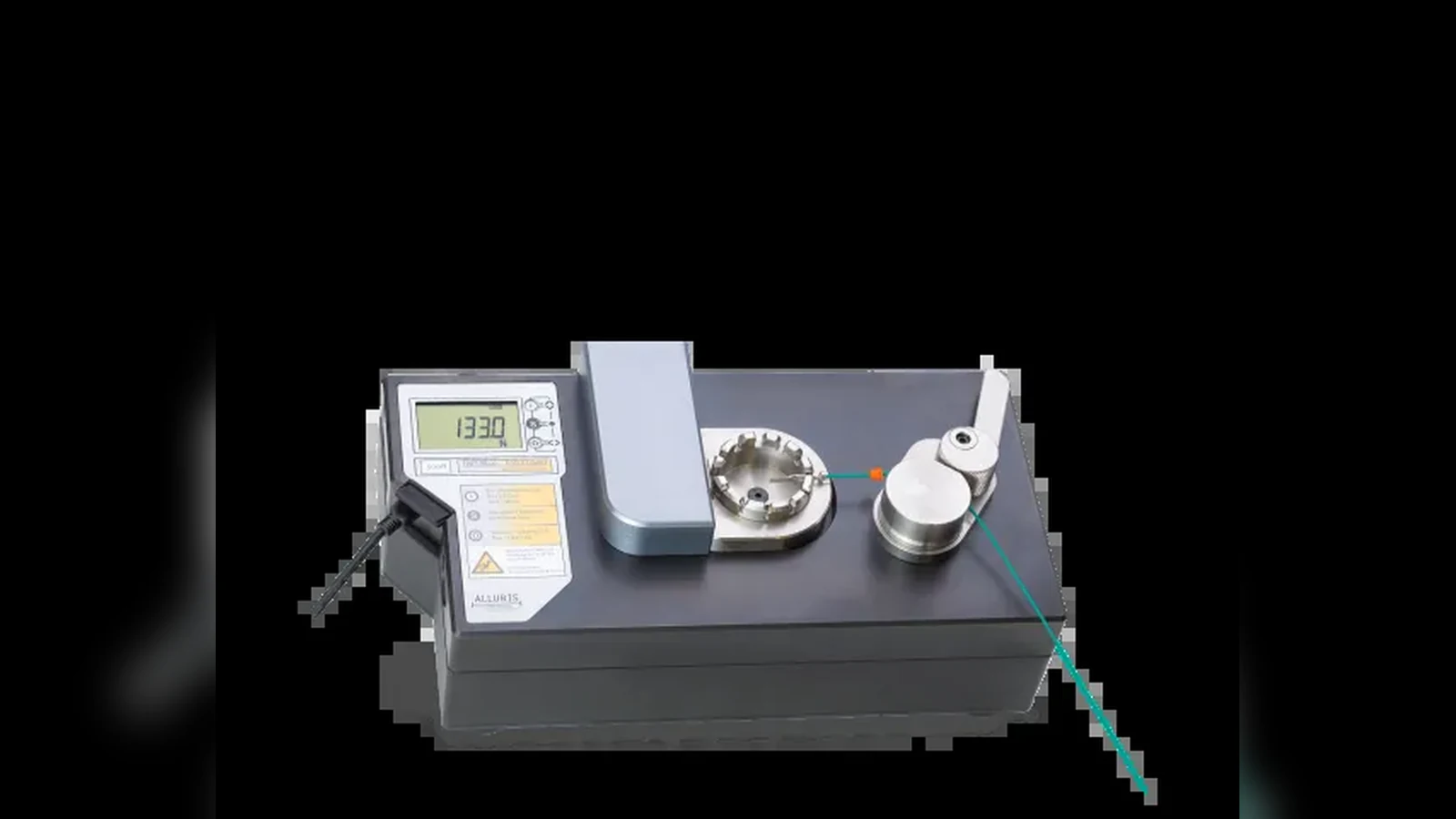
A pull test can expose strand damage, poor compression or tooling variation, but there is no universal force that validates every robot connector. Follow the terminal maker’s test method, wire size, conditioning rule, pull rate and minimum value. Destructive samples belong in process qualification or scheduled sampling, not back in the robot. For field repairs, document the matched parts, visual checks and retention result, and replace uncertain crimps rather than “testing” them with an uncontrolled hard tug. Keep the approved contact, tool and wire combination on the build traveler so substitutions trigger a fresh specification check. Photograph one accepted sample beside its traveler for later visual comparison.