Most classroom robot vision failures look like software problems at first. The image freezes, the stream drops, latency jumps, or the camera behaves differently after the robot is moved. Before rewriting the pipeline, teams should ask a simpler question: is the camera wiring plan right for the job?
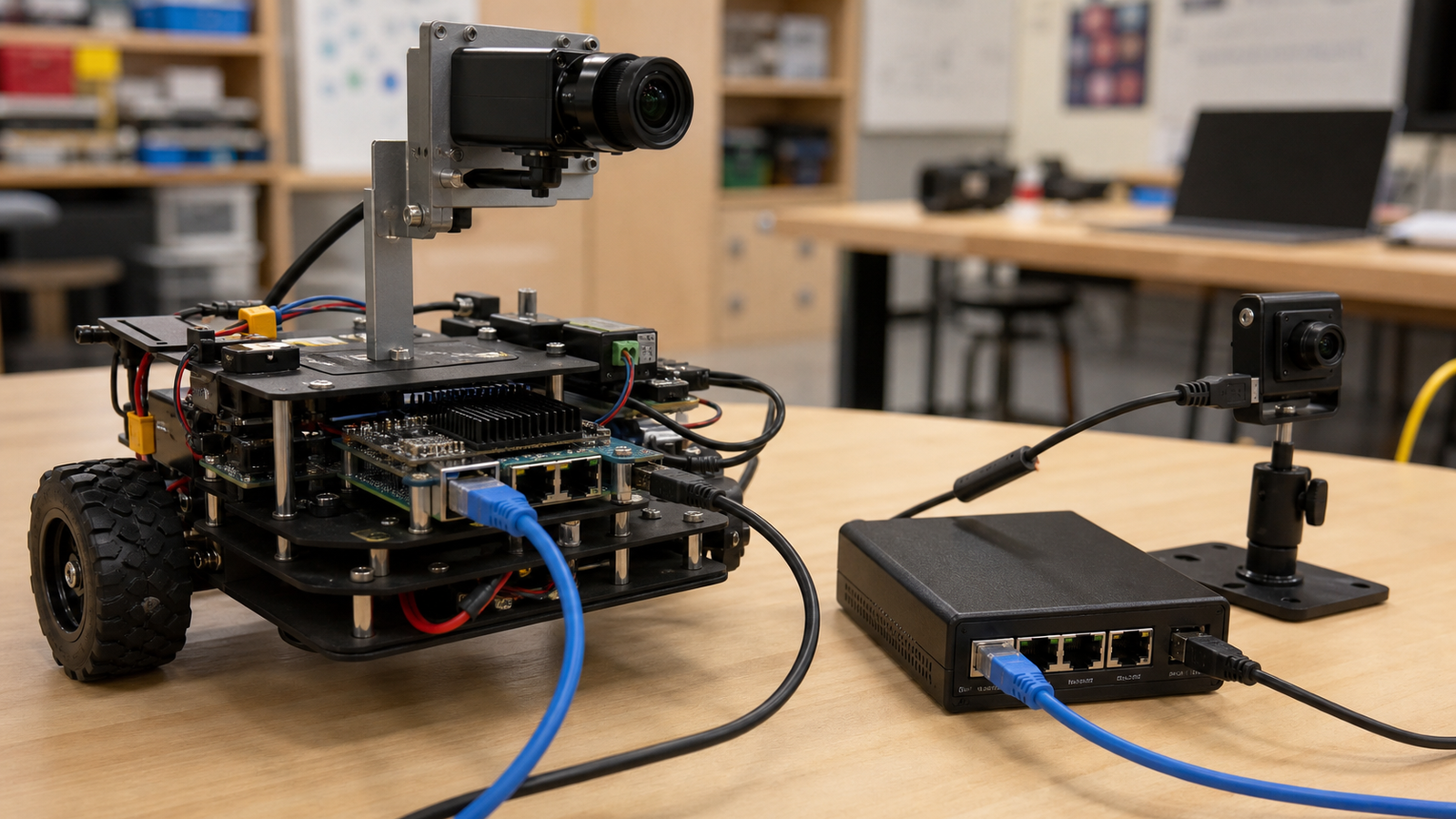
PoE and USB-C can both work well, but they solve different problems. PoE is attractive when the camera needs one cable for power and data across a longer run. USB-C is attractive when the camera is close to the controller and the build benefits from common cables, compact adapters, and simple desktop debugging.
Quick answer
Choose PoE when the camera is mounted away from the computer, when cable retention matters, or when a central switch makes power cycling easier. Choose USB-C when the camera is close to the processor, the robot is small, and the team needs the lowest-friction setup for experiments and code workshops.
PoE strengths
- Distance: Ethernet cabling gives teams more layout freedom than short USB camera cables.
- Power control: A managed PoE switch can make resets cleaner during demos or lab work.
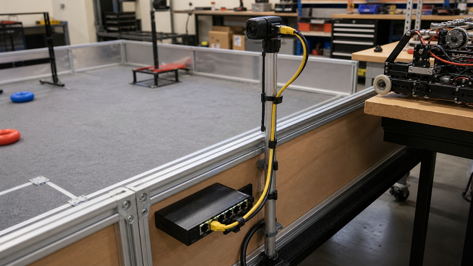
- Field layout: One cable can be easier to route through a cart, field wall, or fixed camera mast.
PoE also encourages teams to think like system builders. They must plan switch placement, cable strain relief, IP addressing, and what happens when multiple cameras share the network.
USB-C strengths
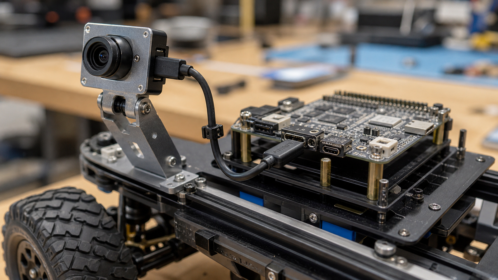
- Simple bench setup: Students can plug the camera directly into a laptop, Raspberry Pi, or robot controller.
- Low parts count: Fewer switches and injectors can mean fewer setup mistakes.
- Fast iteration: USB cameras are often easier to swap during a lesson or prototype sprint.
The catch is that USB-C does not automatically mean durable field wiring. Short cables, loose adapters, and unclear power negotiation can still create hard-to-debug failures.
Checklist before buying
- Where is the camera mounted relative to the processor?
- Does the cable move with the robot, a turret, or an arm?
- Can a student reset the camera without unplugging the whole robot?
- Will the build need one camera now and several cameras later?
- Is the failure mode visible to students during debugging?
This guide pairs with TVG’s MIPI CSI vs USB camera guide and robot vision lighting checklist. Interface, lighting, and mounting all shape the final result before model tuning begins.
TVG Take
Do not choose the camera first and hope the wiring works out. For classroom robots, the wiring plan is part of the vision system. PoE makes sense when the camera behaves more like fixed field equipment. USB-C makes sense when the camera behaves more like a compact prototype part. Either way, document the reset steps and cable limits before students blame the code.
Classroom setup pattern
A practical lab can keep both options available without confusing students. Use USB-C for the first bench lesson, where the goal is to see frames, change exposure, and understand lighting. Move to PoE when the class builds a fixed practice field, remote goal camera, inspection lane, or cart-mounted camera that should stay in place across multiple sessions.
Teachers should also document the reset path. If the camera fails during a demonstration, students should know whether to restart the script, power-cycle a switch port, reseat a cable, or check a hub. That troubleshooting flow is part of the curriculum because it mirrors the way real robot systems are maintained.
Sources
- Raspberry Pi camera software documentation
- TVG: MIPI CSI vs USB cameras for maker robots
- TVG: Robot vision lighting checklist