A mobile maker lab lives or dies by small parts that rarely make the equipment list: short cables, adapters, strain relief, power meters, and network spares. The robot, camera, 3D scanner, portable monitor, or field dashboard may get the headline, but the connector kit decides whether the setup survives a classroom floor, a competition pit, or a weekend field test.
This guide is for STEM programs, robotics teams, creator labs, and small engineering groups that move equipment between benches. It focuses on durable choices rather than brand recommendations: USB-C Power Delivery behavior, HDMI and UVC capture paths, Ethernet fallbacks, cable length, labeling discipline, and test habits.
Quick answer
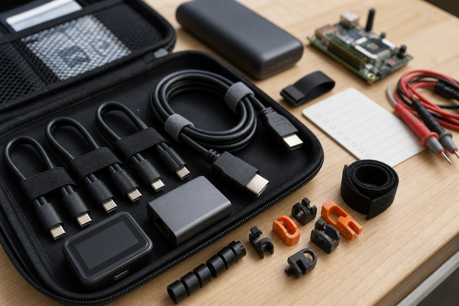
Build the kit around known-good short cables, not a drawer of mystery adapters. Carry at least two certified USB-C PD cables, a small USB-C power meter, a USB-C to 2.5G Ethernet adapter, short HDMI cables, one UVC capture dongle, spare microSD or USB storage, cable ties, strain relief, and a printed connection map for the common setups your team actually uses.
Why USB-C PD is the first failure point
USB-C is physically convenient, but it hides several different behaviors behind the same reversible connector. A cable may support charging only, USB 2.0 data, high-speed USB data, DisplayPort Alternate Mode, or higher current through an e-marker. The USB-IF Power Delivery overview is a reminder that the power negotiation is a protocol, not just a plug shape.
For maker teams, the practical rule is simple: separate charging cables from data/video cables and mark them visibly. A USB-C cable that charges a tablet may not carry a camera feed. A cable that works on the bench may brown out a single-board computer when a motor controller, SSD, or capture card joins the same power path.
Carry a small USB-C power meter, but do not treat it as laboratory instrumentation. Use it to answer field questions: Is the power bank negotiating the expected voltage? Did the device fall back to 5V? Does the current spike when recording starts? Does the system behave differently with a longer cable?
Video paths: HDMI, UVC, and the capture-card trap
Camera and robot-event workflows often include HDMI output, USB webcam mode, or a capture dongle. HDMI is a mature consumer-video interface, but the HDMI Licensing specification page shows why version numbers alone are not enough. Resolution, refresh rate, cable length, and capture-device support matter together.
For UVC devices, the advantage is driver simplicity: many operating systems can see the camera as a standard USB video source. The tradeoff is control. Exposure, focus, compression, and latency can vary by device and app. If the event stream needs reliability, test the exact camera, cable, hub, and recording software before the day of use.
TVG’s recent HDMI capture card specs guide covered capture hardware in more detail. The cable-kit lesson is narrower: every capture path should have a short, known-good HDMI cable, a spare, and a way to confirm whether a blank feed is a camera setting, cable issue, power problem, or capture-device mismatch.
Ethernet still belongs in the case
Wi-Fi is convenient for demos, but a small Ethernet adapter is often the fastest way to debug a stubborn device. The IEEE 802.3 family underpins wired Ethernet, and the IEEE 802.3 standard page is a useful anchor for why cable quality, negotiated speed, and link state matter.
For field kits, 2.5G Ethernet is a practical sweet spot when laptops, mini PCs, NAS boxes, and modern access points support it. It is fast enough for backups and camera offload, more forgiving than fragile high-end setups, and a strong fallback when a crowded venue crushes wireless reliability.
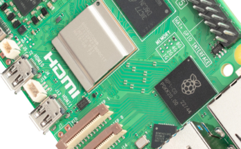
Pair the adapter with a short patch cable and a tiny unmanaged switch if your lab often connects multiple devices. That combination can rescue a robot dashboard, a camera ingest station, or a Raspberry Pi test rack when the local Wi-Fi credentials are unknown or unreliable.
Length, strain relief, and cable routing
Long cables create avoidable ambiguity. A six-foot cable that worked in a quiet room may fail when it is coiled near a power brick, stepped on, or tugged by a moving cart. Short cables reduce clutter and signal problems, but they also need strain relief so devices are not hanging from their ports.
Use hook-and-loop ties, right-angle adapters only where they reduce stress, and a small number of cable clips. Do not overbuild the kit with every adapter on the internet. A smaller set of tested parts is easier to train, inventory, and replace.
What to test before an event
- Power-on sequence: does the system boot correctly when all accessories are already connected?
- Voltage negotiation: does the USB-C power path stay at the expected voltage under load?
- Video capture: does the recorder see the feed at the intended resolution and frame rate?
- Network fallback: can the device be reached over Ethernet when Wi-Fi is unavailable?
- Storage path: can files move from camera or robot logs to backup storage without a cloud account?
- Physical movement: does the setup survive a cart roll, table bump, or student handoff?
Internal links for related TVG workflows
This checklist pairs well with TVG’s portable monitor field dashboard guide and our field camera power workflow guide. Those pieces cover display and camera-power choices; this article focuses on the connector layer that keeps them usable.
TVG Take
The best cable kit is boring, labeled, and tested. Buy fewer adapters, verify them harder, and build the case around repeatable workflows your team actually runs. In a mobile lab, connector discipline is not accessory shopping; it is reliability work.