A 0 mA reading does not identify one failed part. It says the series current path is not flowing—or that the meter never entered that path. Separate the power supply, field wiring, transmitter and receiver before replacing hardware, and coordinate with operations before opening a live control loop.
In a two-wire loop, the same pair powers the transmitter and carries its signal. Four milliamps normally represents the configured lower range and 20 mA the upper range. A true zero is therefore below the live-zero signal and should be treated as a power, wiring, fuse, termination or measurement-topology problem rather than a legitimate process value.
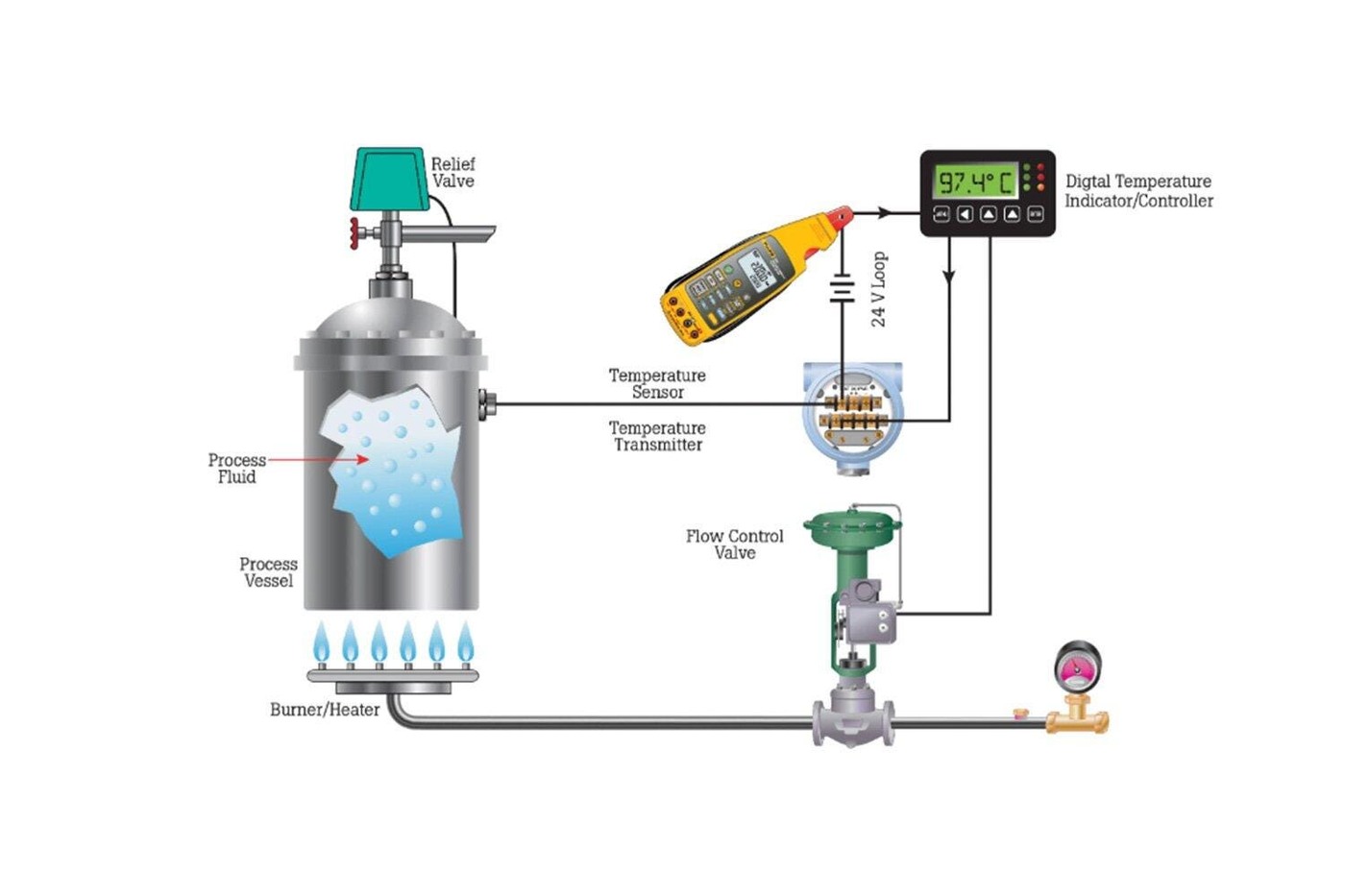
First prove that loop power reaches the open end
De-energize or follow the site’s approved procedure before disconnecting conductors. With the transmitter leads removed and identified, measure DC voltage across the field pair. Fluke’s troubleshooting guidance uses a nominal 24 V loop and says the disconnected transmitter wires should show the full supply voltage. No voltage points upstream toward the supply, an open fuse, an open conductor or a termination fault.
Voltage present at the open pair proves only that the supply path can establish potential with no current. It does not prove that the loop retains enough voltage when 20 mA flows. Corroded terminals, added indicators and long cable runs can consume the reserve only under load.
Measure current in series—or clamp without opening
A conventional meter measures milliamps only when inserted in series. Move the red lead to the mA jack, select DC mA, open one signal conductor and bridge that opening with the meter. Connecting a meter in current mode directly across the supply creates a low-resistance path and can blow the meter or input fuse.
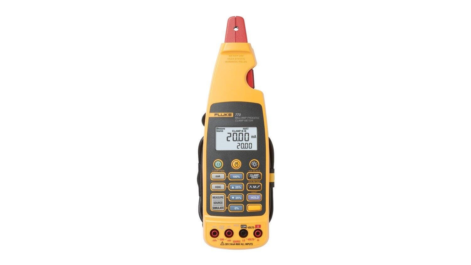
A process milliamp clamp measures the conductor without breaking the loop, after the clamp is zeroed. That is useful when interrupting the signal would trip an interlock or disturb a controller, but the clamp must surround one conductor rather than the entire outgoing-and-return pair. Equal and opposite currents in both conductors cancel magnetically.
Use simulation to split the transmitter from the rest of the loop
A loop calibrator in mA simulate mode replaces the transmitter electrically. It behaves as a controlled current sink and draws power from the loop’s supply. Program 4 mA and the receiver should indicate its lower range; program 20 mA and it should indicate the upper range. If both points track, the wiring, supply and receiver path can carry the command, making the removed transmitter or its sensor input the stronger suspect.
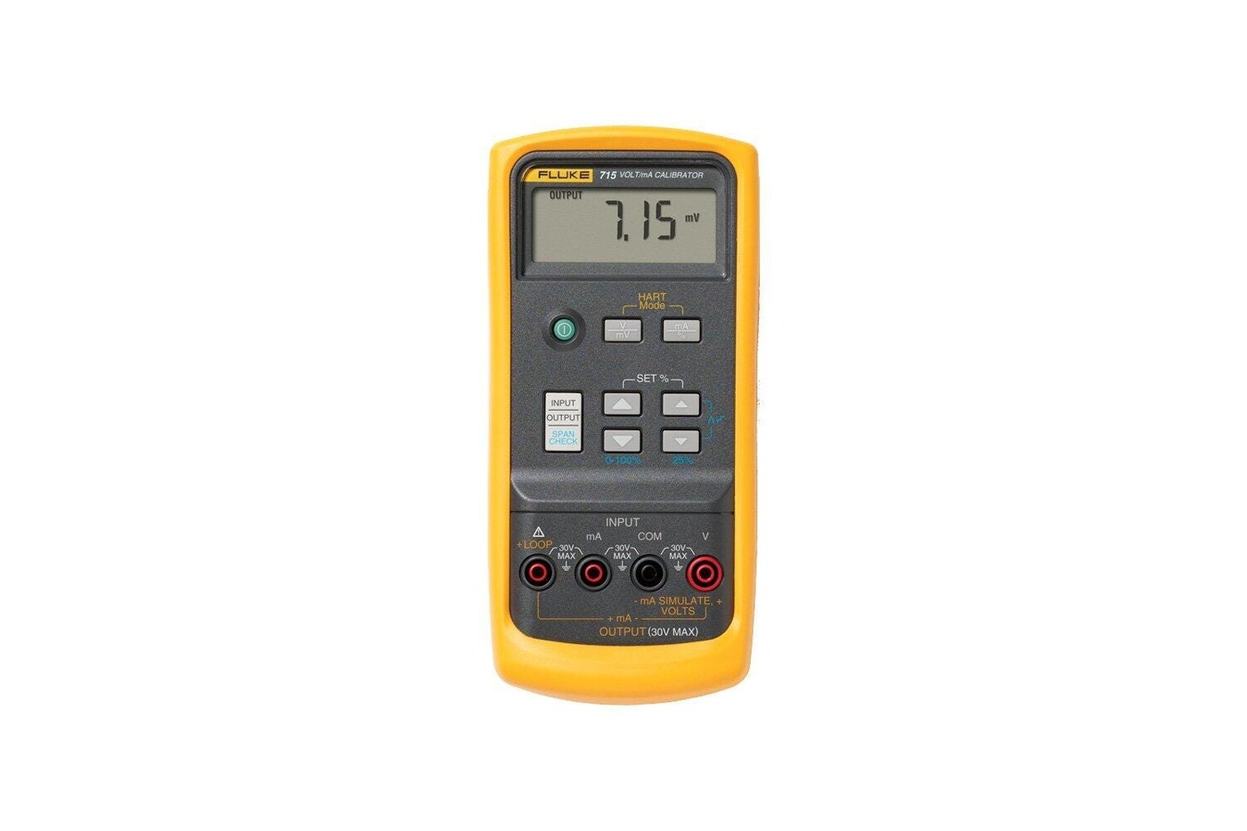
If the simulator reports an open circuit, inspect the input fuse and the receiver path. Fluke notes that an input resistance check may fall between 100 and 250 ohms for the example system. Do not perform resistance or continuity measurements on an energized circuit.
Check the voltage budget at 20 mA
The receiver usually measures the current as the voltage across a burden resistor. A 250 ohm burden produces 1 V at 4 mA and 5 V at 20 mA. Texas Instruments notes that a lower burden preserves more voltage for the rest of the loop and reduces resistor self-heating, although the receiver still needs enough signal for its converter.
Use the full-scale budget: Vreserve = Vsupply − Vtransmitter,min − Imax(Rburden + Rwire + Rother). With 24 V, a 10 V transmitter minimum, 250 ohms of burden and 100 ohms of total wire resistance, the reserve at 20 mA is 7 V. A positive paper margin does not clear a damaged connection; measure the voltage across each segment while the loop is loaded.
Read the result by boundary
- No open-circuit voltage: trace supply, fuse and continuity toward the controller.
- Voltage present, but no series current: verify polarity, transmitter connection and that the meter fuse/jack are correct.
- Simulator drives 4 mA and 20 mA correctly: the controller path is responding; investigate the transmitter and sensor side.
- Current is correct but the HMI is wrong: check input scaling, burden value and input-card calibration.
- Failure appears near 20 mA: check loaded voltage drops and loop reserve rather than assuming a bad zero adjustment.
The safest useful conclusion is a located boundary, not a guessed component. Record current, open-circuit voltage, loaded segment drops and the receiver indication together; those four observations keep a wiring defect from being “fixed” by an unnecessary transmitter replacement.