A filament runout fault can come from the filament path, sensor, cable, firmware, or print host. First record the exact printer, controller-board revision, firmware version, and whether the job came from an SD card, USB sender, OctoPrint, or another host. Vendor Marlin branches may alter the commands below.
Identify the sensor before testing it
A presence sensor answers a binary question: is filament physically pressing a switch, blocking an optical path, or moving a lever? It should change state when filament is inserted or removed, even while the printer is idle.
A motion or encoder sensor watches movement while extrusion is commanded. Filament can remain inside it while a jam, stripped filament, or stationary spool causes an event. It may output pulses rather than a steady “present” reading.
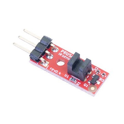
Classify the symptom in both directions
- False runout: the printer pauses with usable filament present. Check lever travel, debris, connector seating, cable flex, polarity and—on motion sensors—spool drag, drive slip, encoder grip and movement distance.
- Missed runout: printing continues after filament is absent or stationary. Check whether detection is disabled, the mechanism is stuck, the signal or polarity is wrong, or the host ignores the pause request.
Before swapping parts, prove whether the mechanism changes, the controller sees it, and a real print responds.
Inspect the path and wiring safely
- Unload filament according to the printer’s procedure, let hot components cool, and switch off and unplug the printer before opening an electronics enclosure or reseating a sensor cable.
- Check the sensor entrance, PTFE guide, lever, roller, and encoder wheel for broken filament, dust, deformation, or misalignment. Filament should follow its normal printing path rather than an artificially straight hand-fed path.
- Trace the cable for crushed insulation, tight bends, strain at the moving toolhead, backed-out terminals, and a partly seated plug. Compare connector orientation and pin positions only with documentation for the exact board and sensor revision.
Never hot-plug the sensor unless the manufacturer explicitly permits it. Do not short unknown pins to “simulate” runout: a connector may carry supply voltage alongside signal and ground, and an incorrect bridge can damage the sensor or controller.
Read the raw input on Marlin
Where the installed Marlin build supports it, connect through a trusted terminal and send M119. Marlin reports endstops as open or TRIGGERED, and its documentation states that filament runout sensors are also reported. Capture the complete response with filament absent, then insert filament fully and run M119 again. A presence sensor should show a repeatable change. Repeat several times and, without entering the printer’s moving envelope, gently flex only the accessible cable to reveal an intermittent connection.
If the mechanism moves but the reported input never changes, power down and recheck the cable. Likely causes then include a failed sensor, wrong board pin assignment, or wrong active polarity. Pin selection, pull-ups, and FIL_RUNOUT_STATE are normally build-time settings in Configuration.h or the board pin map—not M412 adjustments. Use firmware for the exact board. A vendor branch may omit or relabel the sensor in M119.
Check Marlin’s runtime behavior with M412
Send M412 with no parameters and save the report. In standard Marlin, M412 S1 enables runout handling and M412 S0 disables it. The D value sets runout distance: too little can create nuisance events, while too much delays a real stop. On supported motion sensors it is the commanded extrusion allowed without a movement reset. Change it only after the raw input is reliable, then re-query after reboot because EEPROM or start G-code may override it.
Test the response in a real print context
A raw transition does not prove that a job will pause. Marlin commonly invokes M600, which may be absent from a vendor build or handled differently by a print host. Review the terminal log for filtered, replaced or immediately resumed commands.
Run a short, supervised print and trigger the sensor only by the manufacturer’s safe method. Confirm that the printer pauses, preserves the job, accepts new filament and resumes; then confirm that normal filament movement does not cause a pause.
Prusa MK2.5S and MK3S: use Sensor info
The following procedure is limited to the Original Prusa MK2.5S and MK3S covered by Prusa’s linked IR-sensor guide; do not transfer its wiring details to newer Prusa models. On the printer, open Support > Sensor info. With no filament inserted, the IR value should be 0. Insert filament: it should change to 1. Remove and reinsert it several times.
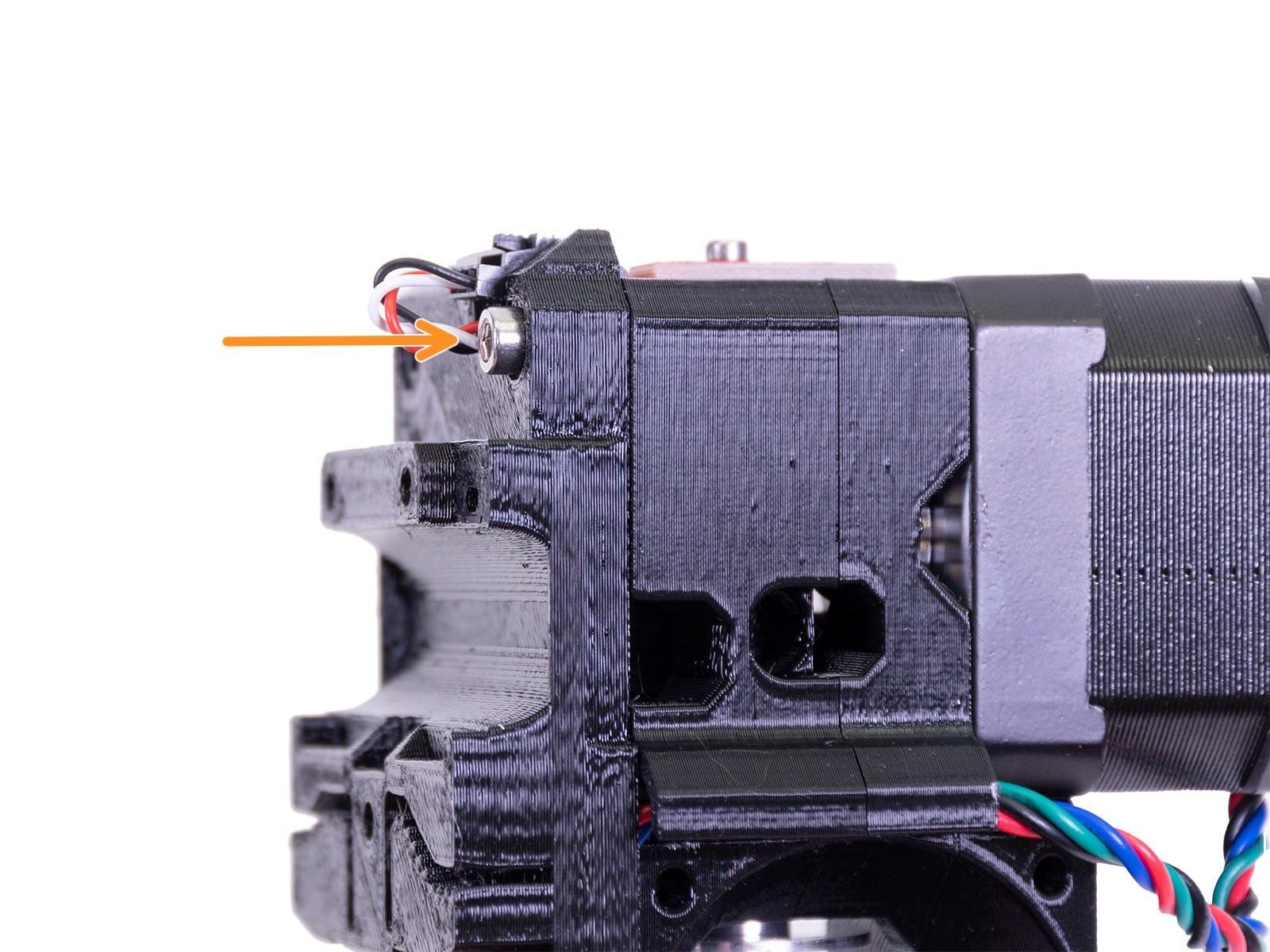
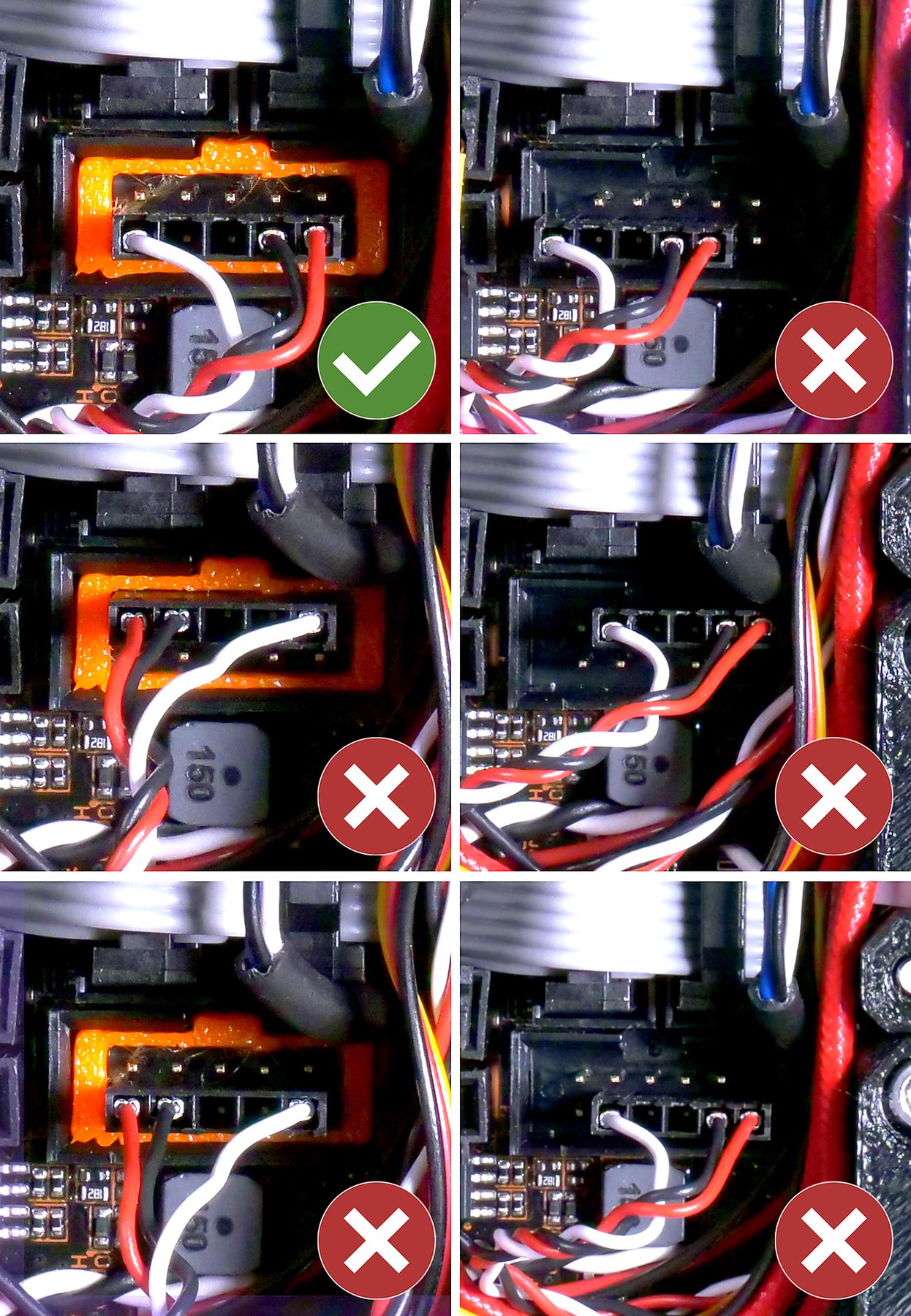
If the value does not change, observe the small mechanical lever. Filament moves it to trigger the IR sensor, so debris, incorrect assembly, or restricted travel can mimic an electronic failure. With power disconnected, inspect the wiring. Prusa specifies that the motherboard connector sits on the bottom row, covers all pins, and has the red wire on the right. The cables differ: on the MK2.5S, the white wire is shifted one pin to the right. Follow the official illustration rather than repinning from memory.
What the results mean
- Mechanism fails: clear or correct the filament path, lever, or encoder coupling.
- Mechanism works, raw report does not: inspect the powered-off wiring, then verify the exact sensor, board pin map, and firmware polarity.
- Raw report works, no print response: check
M412, runout distance, the configured script,M600support, and host behavior. - Only motion causes faults: inspect cable flex and filament transport, then evaluate the encoder and distance threshold.