
Ringing is a decaying series of ripples that follows a sharp corner or sudden direction change on an FDM print. Treat it as a motion-system problem first: secure the printer, inspect belts and pulleys, then establish a repeatable acceleration baseline. Tune input shaping only after the mechanics are sound.
Start with the pattern, not the setting
True ringing repeats after an edge and fades with distance from that edge. The spacing is often consistent along one axis because the printer structure is oscillating at a resonant frequency. Random roughness, a single bulge at a corner, periodic Z-banding and extrusion changes across an entire wall point toward different fault chains.
Use side lighting and compare the X-facing and Y-facing walls. If the echoes appear after direction changes on one axis more than the other, keep that axis in view during the mechanical checks. Do not diagnose from one complex model whose curves, infill and variable speed hide the trigger.
Fix hardware before firmware
Prusa’s ghosting guidance starts with X/Y belt condition, print speed and a firm support surface. That order is useful across many Cartesian and CoreXY machines. With power off and the printer cool, check that the machine does not rock; frame fasteners, toolhead, bed and spool mount are secure; belt teeth are intact; pulleys do not slip on motor shafts; and idlers rotate without obvious binding.
Belts need the manufacturer’s specified tension, not maximum tension. A loose belt can introduce backlash and poor control, while an overtight belt increases bearing and motor load. On printers with model-specific tension tools or frequency targets, use those instructions. A generic “guitar string” test is only a coarse warning, not a universal value.
Establish one controlled baseline
Print a simple model with sharp X and Y corners using one material, temperature, layer height, speed profile and orientation. Record the firmware configuration and slicer acceleration controls. Klipper’s resonance guide specifically warns against rotating its test model because the marked walls correspond to printer axes; the broader lesson is to keep geometry and orientation fixed while changing one variable.
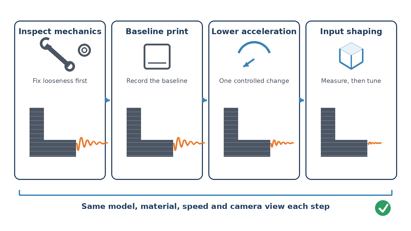
Photograph the same corner under the same light and camera distance. That creates a comparison record. Without it, a smaller-looking echo may simply be a different wall, angle or surface reflection.
Change acceleration before chasing speed
Ringing is excited most strongly by rapid changes in motion. A printer may reach a high nominal speed only briefly, while aggressive acceleration repeatedly injects vibration at corners. Reduce acceleration for the affected axis or external perimeter and reprint the same model. If the echo amplitude falls while its spacing remains similar, the test supports a resonance diagnosis.
Do not stack multiple fixes in one run. Changing belt tension, acceleration, jerk or square-corner velocity, and input shaping together may improve the part, but it will not show which change mattered or whether a mechanical defect remains.
Tune input shaping last
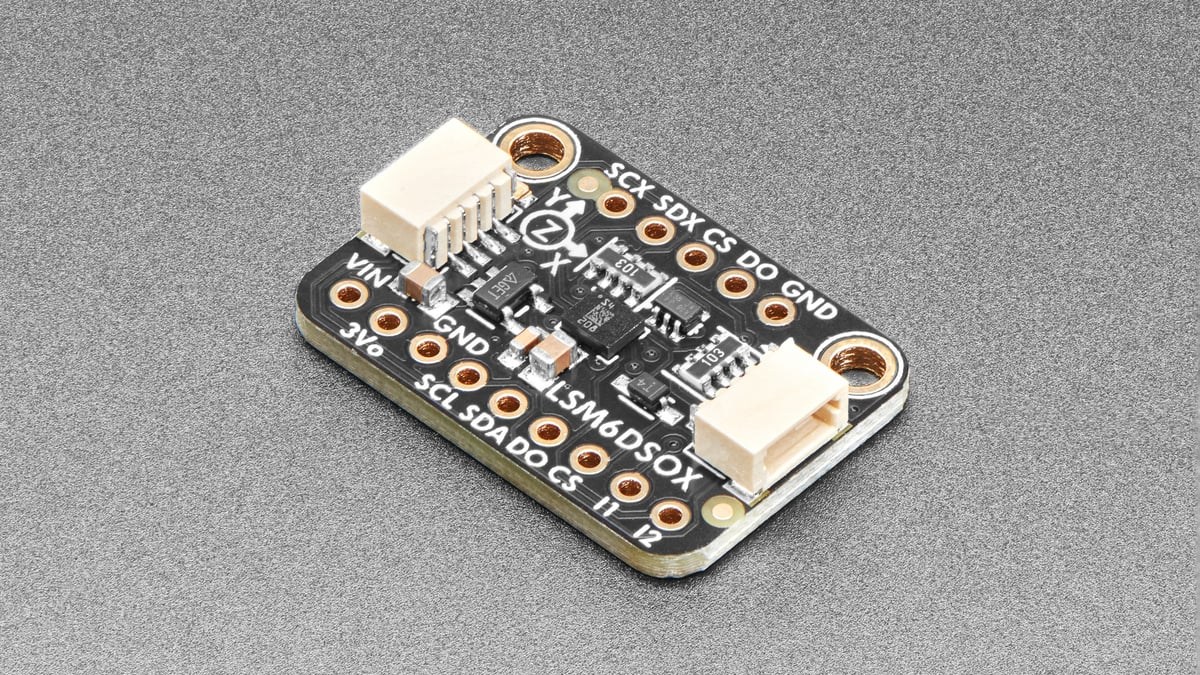
Input shaping modifies commanded motion to avoid exciting measured resonances. Klipper provides manual and accelerometer-based tuning workflows; Marlin exposes ZV shaping through M593 on supported builds. Follow the firmware’s own procedure, save the measured frequencies and test the same corner again.
Compensation has a trade-off. Klipper notes that unsuitable shapers or excessive smoothing can soften fine details. The target is not the highest acceleration that can be entered in a configuration file. It is a stable setting that reduces echoes without erasing the geometry the printer is meant to reproduce.
When the defect is not ringing
A bulged corner that does not decay may involve pressure or linear advance. Regular bands tied to layer height may be Z-axis mechanics. Roughness everywhere can come from extrusion, temperature or wet filament. Return to the visual pattern before adding more resonance compensation.
For another baseline-first diagnostic method, see TVG Report’s 3D-printer nozzle-wear guide.

My experience with a 10mm belt showed that the noise reduced significantly when I switched to a 20mm one.