Robot power problems often get blamed on code, motor controllers, or “bad batteries” before anyone looks at the connector. Then the team discovers the real failure: a battery lead tugging on a crimp, a connector bouncing against a chassis rail, a cable rubbing near a wheel, or a wire bundle with no strain relief. The electrical bug was mechanical first.
This support guide is aimed at small robot teams, STEM labs, and maker projects. It is not a replacement for competition rules, manufacturer instructions, or electrical safety supervision. The goal is to make connector strain relief part of the design review instead of a cleanup step before inspection.
Quick answer
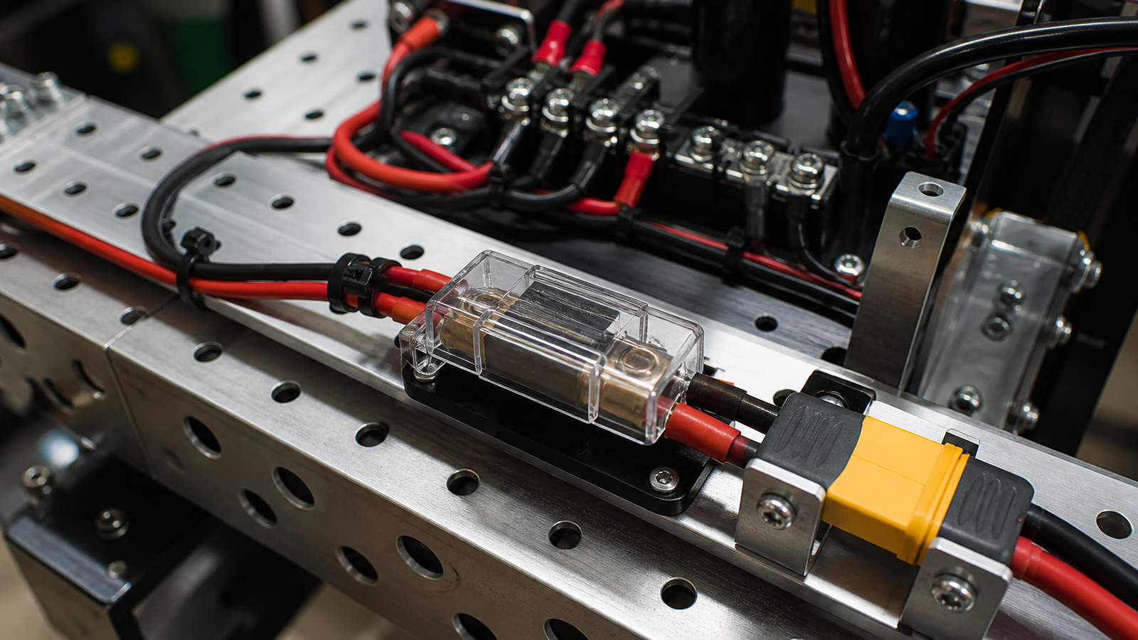
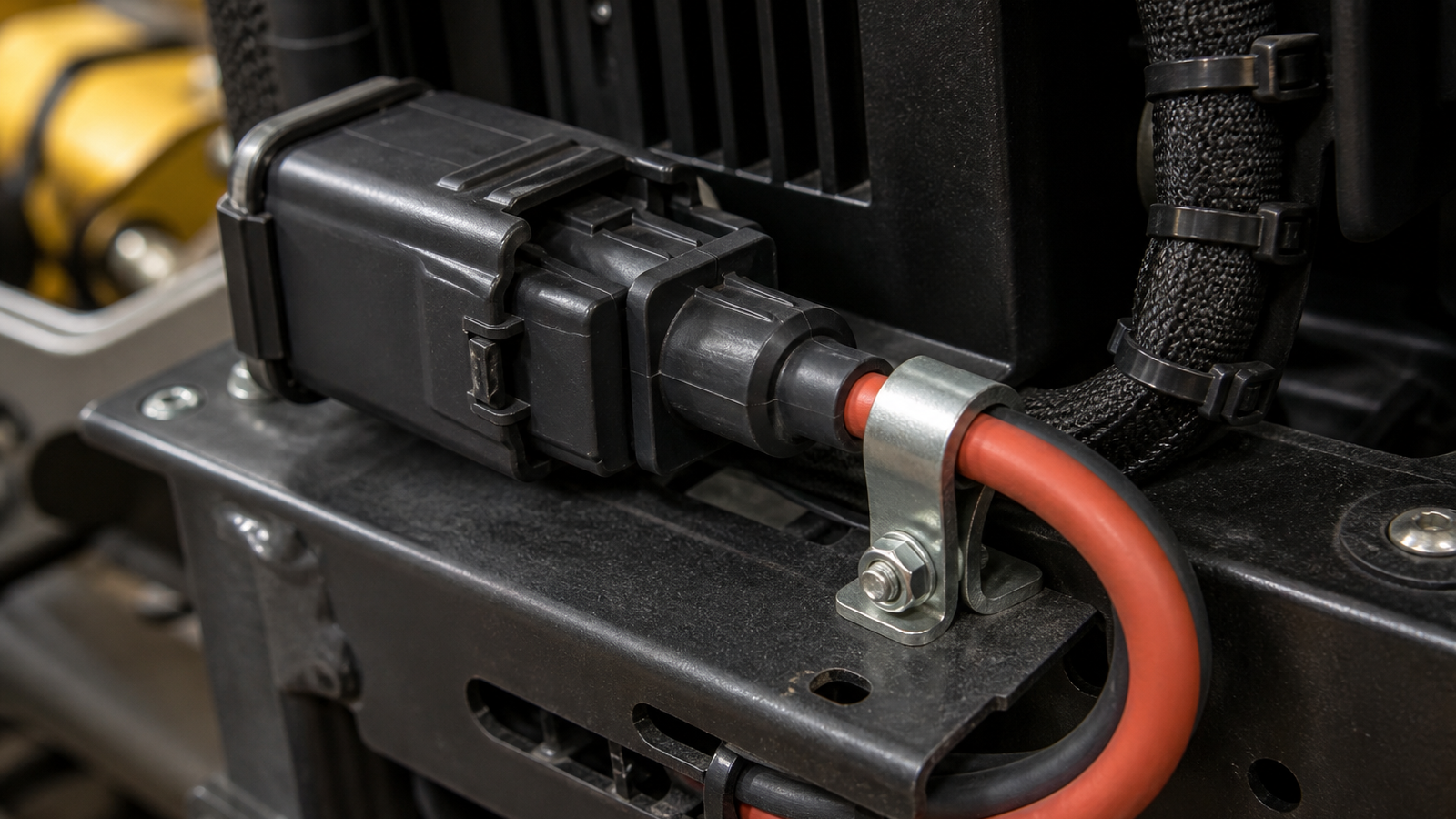
Treat the battery connector, fuse or breaker, wire gauge, crimp, mounting point, and cable path as one mechanical-electrical system. The connector should mate fully, stay protected from impacts, and avoid carrying the full weight or pull of the battery lead. Add strain relief close enough to matter, but not so tight that it damages insulation or makes service impossible.
Why strain relief matters
A robot is a vibration machine. It accelerates, turns, collides with field elements, and gets carried between matches or demos. Even a connector rated for the current can fail if repeated motion works the crimp, loosens a terminal, or bends the cable sharply at the housing. Power interruptions may appear as brownouts, random resets, radio drops, motor glitches, or intermittent sensor failures.
Connector families such as Anderson Powerpole are common in robotics because they are modular and widely supported, but the connector choice is only one part of the system. The assembly quality, contact insertion, wire support, and route through the chassis matter just as much.
Troubleshooting checklist
- Inspect the crimp: Look for loose contacts, exposed strands, poor insertion, discoloration, or movement inside the housing.
- Check the bend radius: Avoid sharp bends immediately behind the connector.
- Add a service loop: Leave enough slack to connect and disconnect safely without yanking terminals.
- Tie down the heavy cable: The battery lead should be supported by the chassis, not the connector shell alone.
- Protect from motion: Keep cables away from wheels, chain, belts, arms, and pinch points.
- Reproduce the failure: With the robot disabled and supervised, gently move the harness while watching voltage and logs.
TVG Take
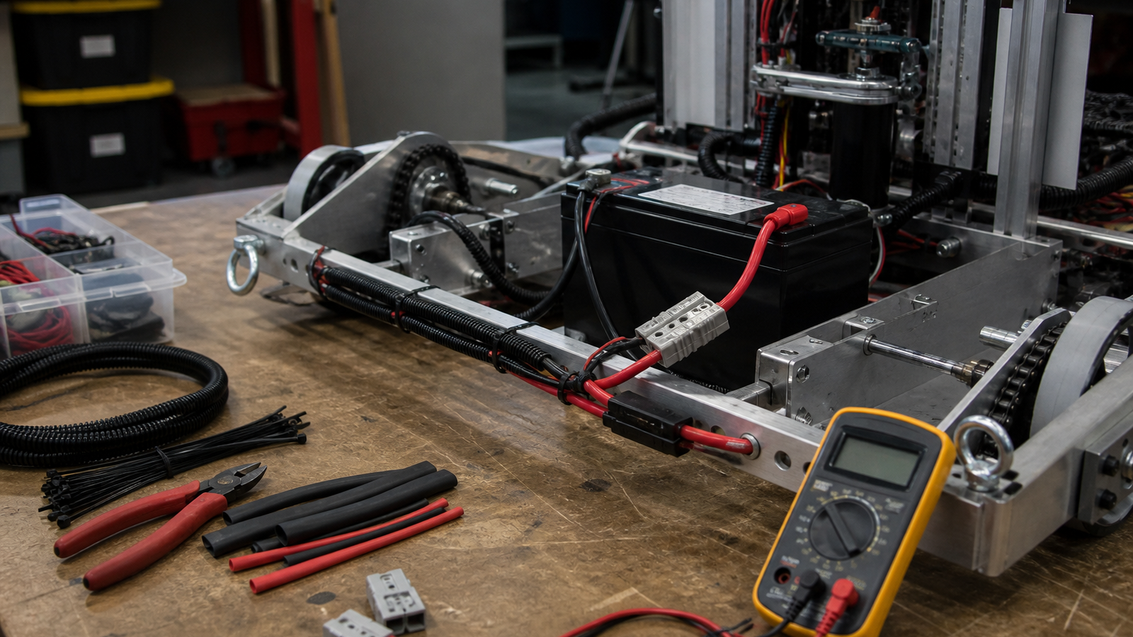
Battery connectors are small parts with system-level consequences. A robot can have good software, good motors, and a fresh battery and still fail because the harness turns every hit into a connector test. For teams trying to build reliable machines, strain relief is not decoration. It is part of the power architecture.
What to document before the next match
A good pit checklist records more than battery voltage. It should include connector inspection, cable tie condition, fuse or breaker mounting, harness rub points, and whether the battery can shift during acceleration. Photos can help: take one clean reference photo of the power path and compare the robot to that picture after transport.
The best time to fix strain relief is before the first intermittent reset. Once a robot has a mysterious power problem, teams often lose hours chasing software symptoms. A physical inspection habit gives students a faster path from symptom to cause.
Related TVG reading
- Robot Camera Field of View Is a Calibration Problem, Not Just a Lens Spec
- PoE or Wi-Fi for Robot Cameras? Reliability Matters More Than Convenience
- Yahboom ROSMASTER X3 Plus Review Preview: A ROS Robot Worth Testing