A 3D scanner spec sheet can look simple until a maker lab tries to use the data for a printed replacement part, robot bracket, enclosure fit check, or classroom metrology demo. The headline number may say “0.05 mm accuracy,” but that does not tell you how the scanner behaves across a larger object, whether the mesh is detailed enough to capture a small edge, or whether a novice operator can repeat the result on a shiny or dark surface.
This guide is for maker labs, STEM robotics teams, repair shops, and small prototyping groups that need to decide whether a phone LiDAR scan, structured-light scanner, desktop scanner, or handheld unit is good enough for the job. It builds on TVG’s related comparison of phone LiDAR versus handheld 3D scanners and connects to field documentation workflows such as action-camera mounting for robotics teams.
Accuracy is not the same as precision
Artec 3D explains the difference in practical terms: accuracy is how close a measurement is to the true value, while precision is how consistent repeated measurements are. A scanner can be precise and still wrong if it repeats the same biased measurement. It can also produce a detailed-looking mesh that is not dimensionally reliable enough for a bracket, jig, or inspection task.
For maker labs, that distinction matters because many projects are not pure visualization. A 3D scan of a sculpture, toy, or classroom artifact may only need visual fidelity. A replacement clip, robot sensor mount, custom panel, or printed fixture needs dimensional trust. The lab should ask what tolerance the part actually needs before shopping by the smallest advertised number.
Single-frame accuracy is the easy number to market
Many scanners advertise a single-frame or single-scan accuracy figure. That number can be useful for comparing devices under controlled conditions, but it is not the whole story. The result depends on calibration, operator technique, surface finish, lighting, distance, temperature, tracking quality, software alignment, and the size of the object being scanned.
A maker team scanning a 40 mm gear tooth has a different problem from a team scanning a 700 mm robot chassis. The small object may need fine mesh detail and a stable fixture. The larger chassis may expose tracking drift, alignment error, and accumulated geometric distortion. A scanner that is acceptable for organic shapes may not be acceptable when mounting holes have to line up.
Volumetric accuracy is the overlooked spec
Revopoint describes volumetric accuracy as the scanner’s ability to reproduce dimensions across a volume of space, rather than just in one frame. That is the spec to look for when a scan is built from multiple captures or when the part is physically larger than the scanner’s most comfortable working area.
The practical test is simple: ask whether the scanner can maintain useful dimensional accuracy across the whole object you care about. For a robotics team, that might mean the distance between motor mounts, battery tray slots, or sensor faces. For a repair lab, it might mean the length of a hinge, the spacing between clips, or the flatness of a mating surface. If the scanner drifts across the object, the mesh may look convincing while still being wrong where the design depends on fit.
Resolution tells you what detail can be represented
Resolution is often mixed up with accuracy. In scanning, resolution usually relates to point spacing, mesh detail, and the ability to represent small features. A high-resolution mesh can show surface texture, small ribs, lettering, or shallow grooves, but a detailed mesh is not automatically accurate. For many maker jobs, both matter: resolution captures the shape, accuracy keeps the shape in the right place.
The easiest mistake is buying for resolution alone. A scan that captures every surface bump may be useful for reference modeling, but if the global dimensions are off, it may still require caliper checks and CAD cleanup before printing. Conversely, a lower-resolution scan can be enough for a rough ergonomic reference or classroom visualization if the project does not require tight fit.
Build a lab acceptance test before buying
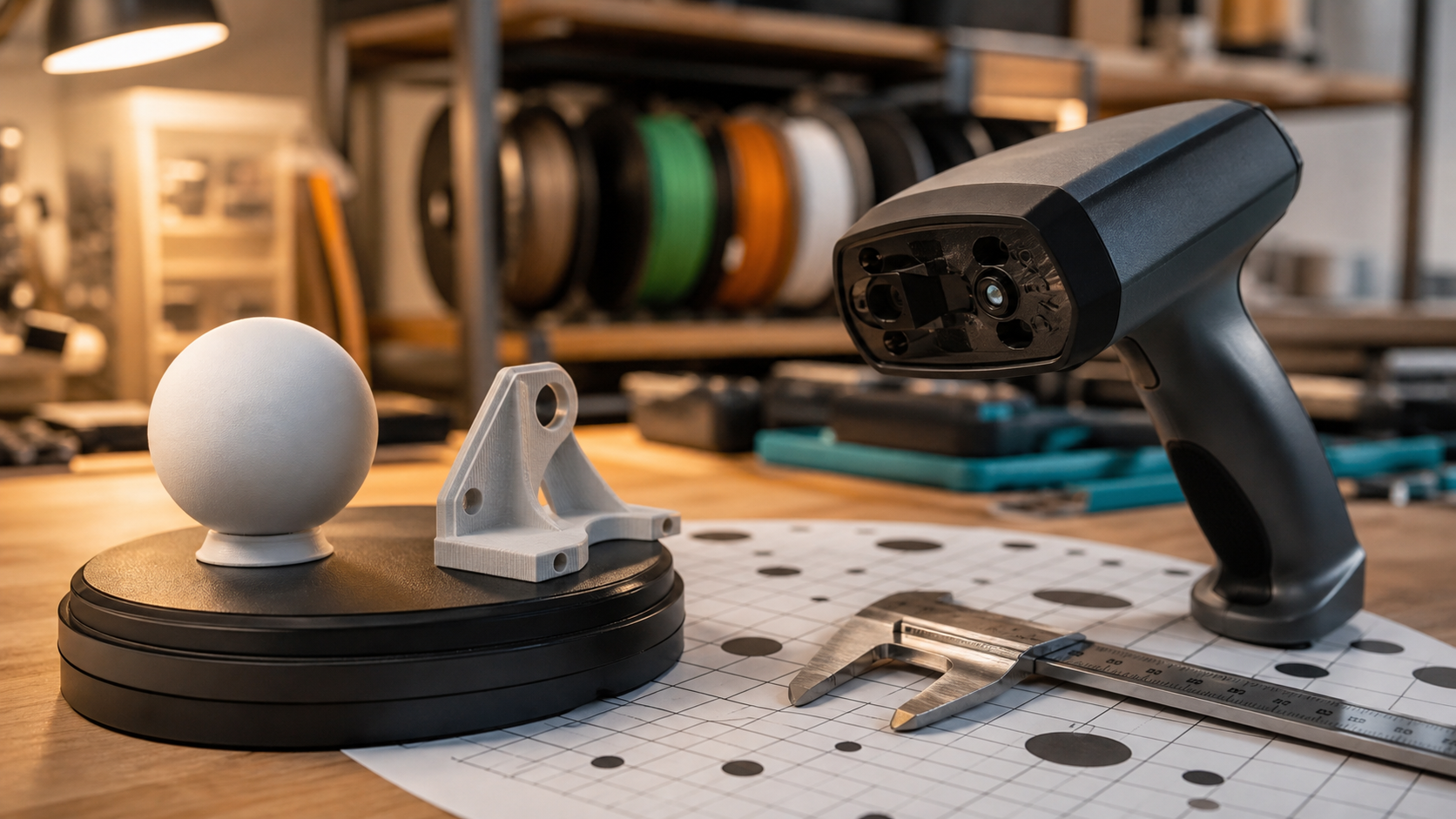
Before a maker lab buys a scanner, it should define three test objects. First, a known-dimension calibration object or gauge that lets students compare scan output against caliper measurements. Second, a typical lab part such as a robot bracket, printed enclosure, or tool handle. Third, a difficult object with a challenging surface: black plastic, reflective metal, transparent material, or a deep cavity.
Run the same scan more than once with different operators. Measure the same features in the resulting meshes. Record calibration steps, lighting, scan distance, turntable use, surface prep, and software cleanup. The goal is not to embarrass a scanner; it is to learn whether the device produces repeatable results in your lab’s actual workflow.
What to check on a spec sheet
- Accuracy: Is the value single-frame, single-scan, or measured across a larger object?
- Volumetric accuracy: Does the vendor publish how error changes over distance or scan volume?
- Resolution or point distance: Is it fine enough for the smallest features your projects require?
- Working distance and field of view: Can students hold the scanner steady at the required distance?
- Surface handling: What happens with dark, shiny, transparent, or thin parts?
- Calibration process: Is calibration quick enough for classroom use, or will it be skipped under time pressure?
- Software export: Can the lab export STL, OBJ, PLY, or formats that fit its CAD workflow?
TVG Take
The best scanner for a maker lab is not always the one with the smallest advertised accuracy number. It is the one that delivers repeatable scans for the lab’s common object sizes, materials, and student skill levels. Treat the spec sheet as a starting point, then build a simple acceptance test that includes caliper checks, repeated scans, and a real print or CAD fit check.
For STEM teams, that acceptance test is also a teaching tool. It shows students why measurement, calibration, and verification matter before a digital model becomes a physical part. That lesson is more valuable than a glossy mesh that looks right but fails at the mounting holes.