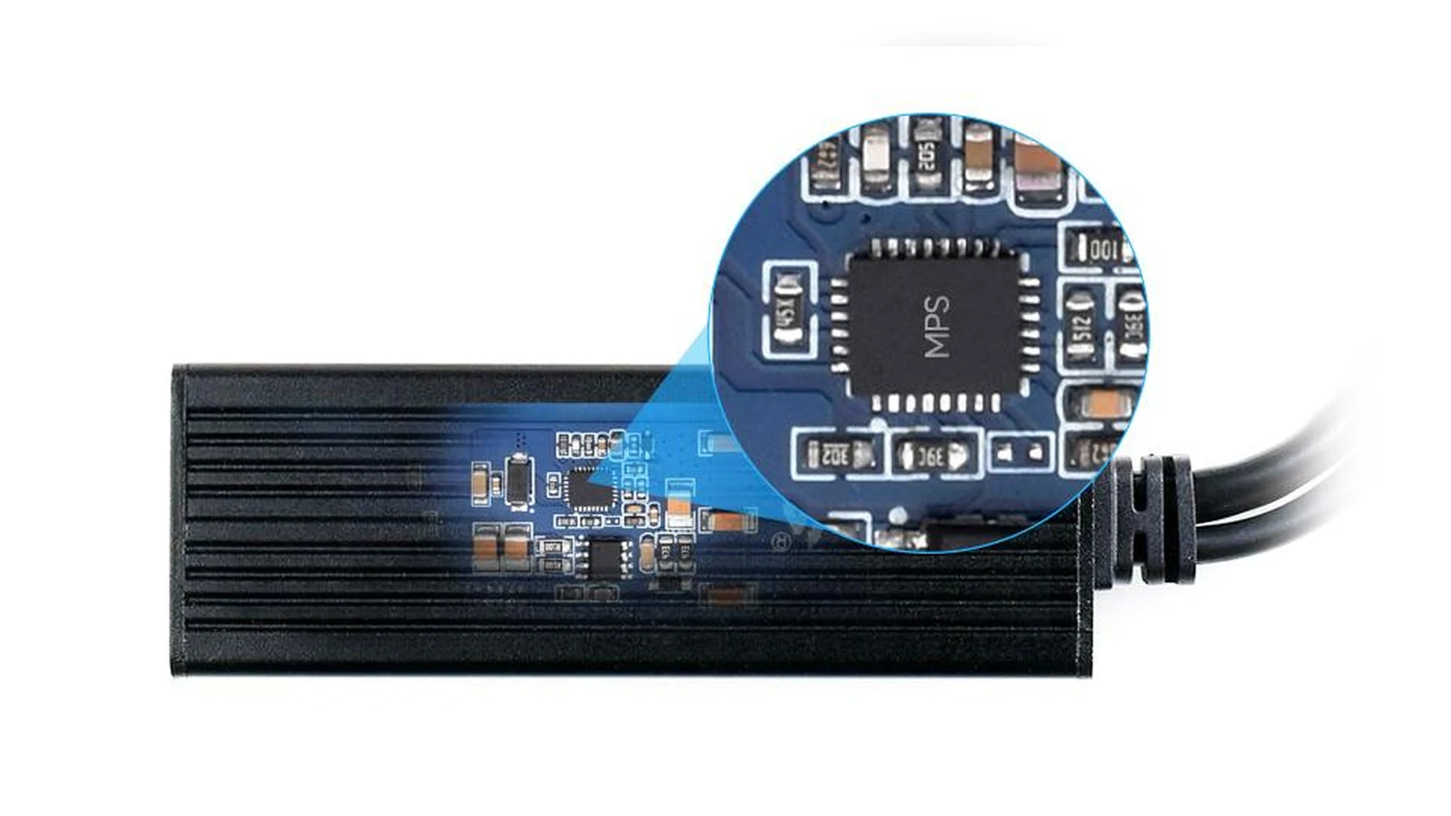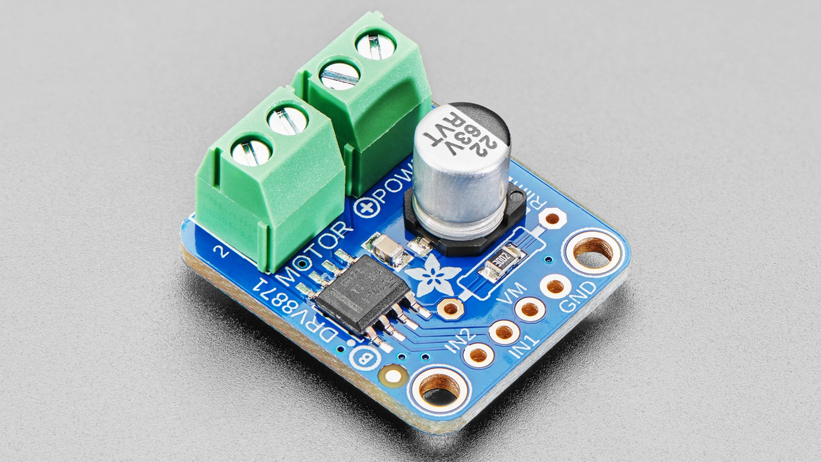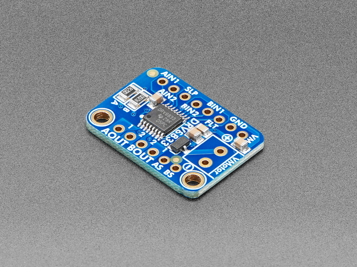
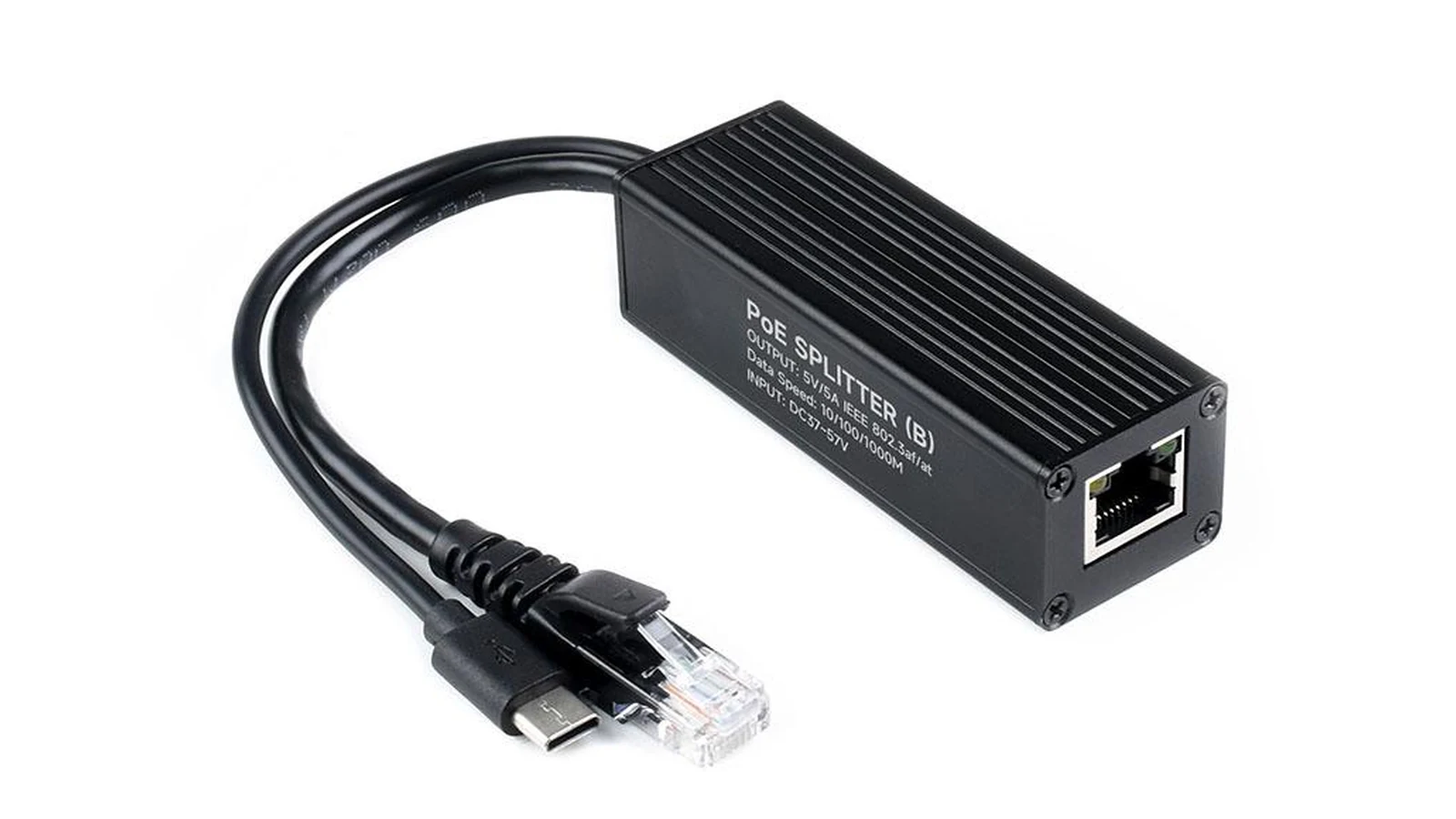
Robot-camera power is a systems decision, not a choice between two familiar plugs. PoE carries data and power over Ethernet to a powered device; a splitter separates that path into the interface the camera or computer actually accepts. USB-C Power Delivery negotiates a power contract between a source and sink. The useful question is where conversion happens and which failure can be serviced.
Map the complete path
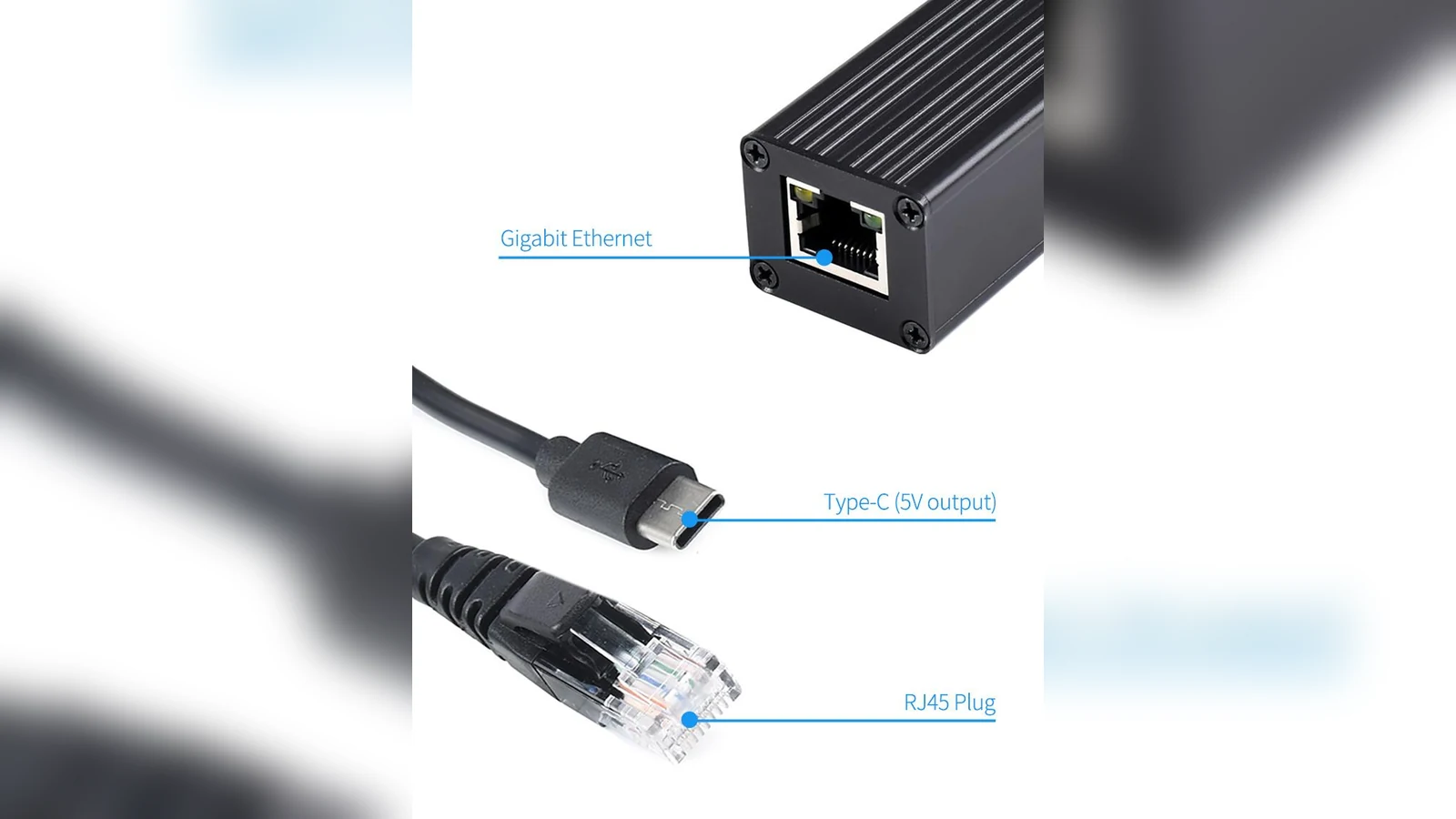
For PoE, record the switch or injector, cable category and length, splitter input, splitter output and camera load. A splitter does not make a non-PoE camera natively PoE: it adds a conversion boundary and another device that can fail. For USB-C PD, record the charger, cable, sink requirements and whether the camera computer actually requests the intended voltage and current.
Choose PoE when the run is the hard part
Ethernet is often easier to route through a building, test cell or mobile rig than a separate low-voltage power lead. Centralized switching can simplify power removal and network service. It also concentrates dependencies: a bad port, injector, splitter or cable can interrupt both data and power. Label both ends and keep a known-good spare path.
Choose USB-C PD when the sink contract is clear
USB-C is convenient near the camera, but the connector does not identify the negotiated power. Check the sink’s documented input range, cable capability and boot behavior. A display on a tester can show the contract; it cannot prove the downstream board remains within thermal limits under camera and compute load.
Commission recovery, not just startup
Test a cold boot, cable reseat, source restart and network interruption. Measure temperatures at the splitter and camera enclosure under the intended load. Record which indicator or log proves the camera is powered, the link is present and the stream has recovered. That record makes the boundary visible when the robot stops seeing.
Measure at the camera, not only at the injector
The useful comparison is the voltage and temperature at the load after the full cable run. A PoE splitter adds conversion loss near the camera, while a USB-C PD supply can add negotiation and cable-resistance variables. Log the camera voltage during boot, infrared illumination and radio transmission, because those peaks are where resets tend to appear. Keep data and power grounds intentional, use strain relief on both connectors, and confirm that the splitter output matches the camera before connection. If the robot already has regulated DC power, a local converter may be simpler; if one Ethernet cable must cross a long fixed route, PoE can reduce wiring without removing the need for load-side checks.