CAN bus problems can feel mysterious to small robot teams because the symptoms look like software bugs: devices disappear, messages arrive inconsistently, motors fault during motion or the robot works on the bench but fails after the wiring is cleaned up.
The first troubleshooting step should be physical. CAN is designed for robust communication, but it still depends on termination, topology, grounding and cable discipline. A team that treats those details as part of the robot design will debug faster than a team that only changes code.
This guide is aimed at educational and small-robot projects where teams may be mixing vendor motor controllers, custom boards, off-the-shelf sensors and student-built wiring. The exact hardware varies, but the debugging habit should be consistent: prove the bus before rewriting the application.
Quick answer
A typical high-speed CAN bus needs termination at the two ends of the main bus, commonly using 120-ohm termination at each end. Avoid star wiring, keep stubs short, verify the bus resistance with power off, and document every node before blaming firmware.
Start with the map
Draw the bus before measuring it. The drawing does not need to be beautiful. It needs to show the main trunk, each controller, each motor or sensor node, the two intended termination points and any branches. Many student teams discover the real problem during this step: the wiring is not a bus anymore.
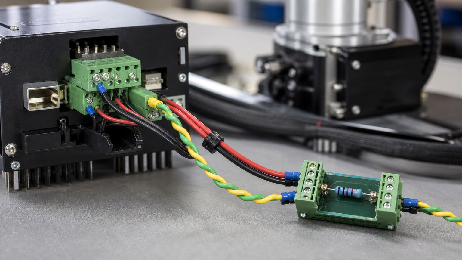
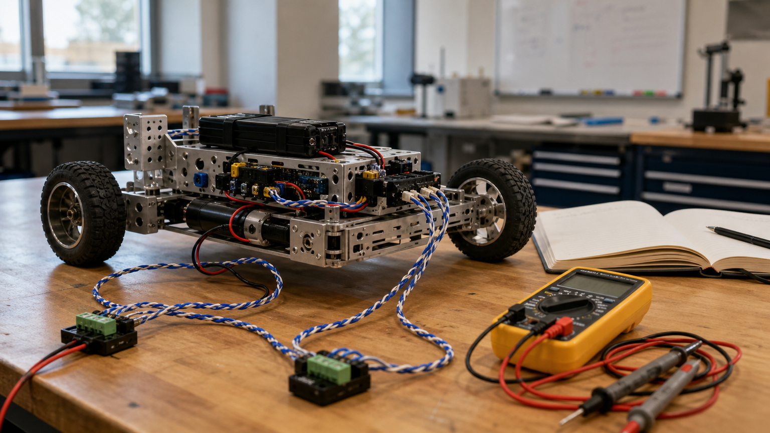
With power off, many teams check resistance between CAN high and CAN low at an accessible connector. A correctly terminated bus with two 120-ohm terminators in parallel is often expected near 60 ohms. That measurement is not a complete health test, but it quickly catches missing, extra or misplaced terminators.
Topology is the next common failure. CAN does not like long star branches. Short stubs to devices are normal in many practical robots, but long branches can create reflections and intermittent behavior. If a device works only when the robot is spread out on a table, the final cable routing deserves suspicion.
Speed also matters. A slow bench network can hide marginal wiring that fails when the team raises the data rate or adds more nodes. If the project has a competition deadline, freeze the bus layout early and treat every added node as a change that deserves a physical-layer retest.
Grounds and connectors matter
Communication wiring does not exist separately from power wiring. Motors, servos and battery leads can inject noise, move connectors or create ground-reference surprises. Keep twisted pairs intact as long as possible, route communication away from high-current switching paths when practical and add strain relief so the connector is not carrying mechanical load.
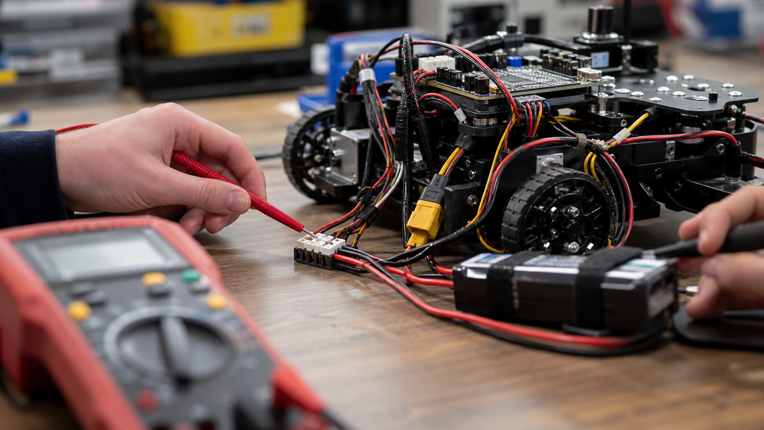
STEM team troubleshooting sequence
- Power down the robot and photograph the current wiring before changing it.
- Draw the actual bus, including every branch and termination point.
- Measure CAN high to CAN low resistance at a convenient connector.
- Disconnect recent additions and retest the simplest known-good bus.
- Check connector polarity, shield/ground practices and strain relief.
- Only then move to logs, firmware versions and message-level debugging.
TVG Take
CAN bus is a great STEM teaching tool because it rewards disciplined engineering habits. The lesson is not just that two wires carry messages. The lesson is that a network is a physical object with ends, branches, connectors and measurement points.
For small teams, the best upgrade may be a laminated bus map, spare terminators and a standard power-off measurement routine. That turns a frustrating intermittent failure into a repeatable lab exercise.
The same routine also teaches restraint. When a robot fails during a match simulation, it is tempting to change code, swap parts and tug wires at the same time. A CAN checklist forces one variable at a time: map, measure, isolate, retest and only then investigate firmware.