Many “software bugs” in small robots are really power problems. A controller reboots during acceleration. A sensor works on the bench and drops out on the field. A camera freezes when a motor starts. The code gets blamed because the wiring fault only appears under load.
This guide focuses on connectors, wire sizing, fusing, strain relief and voltage drop for maker robots. It is not a replacement for a competition rulebook or certified electrical design, but it gives labs a practical checklist before they lose another test session to mystery resets.
Quick answer
Use connectors rated for the current, fuse the battery path, choose wire gauge for the real load and length, measure voltage under load, and strain-relieve every connector that moves with the robot. A connector that fits is not automatically a connector that belongs in the main power path.
Start with current, not connector shape
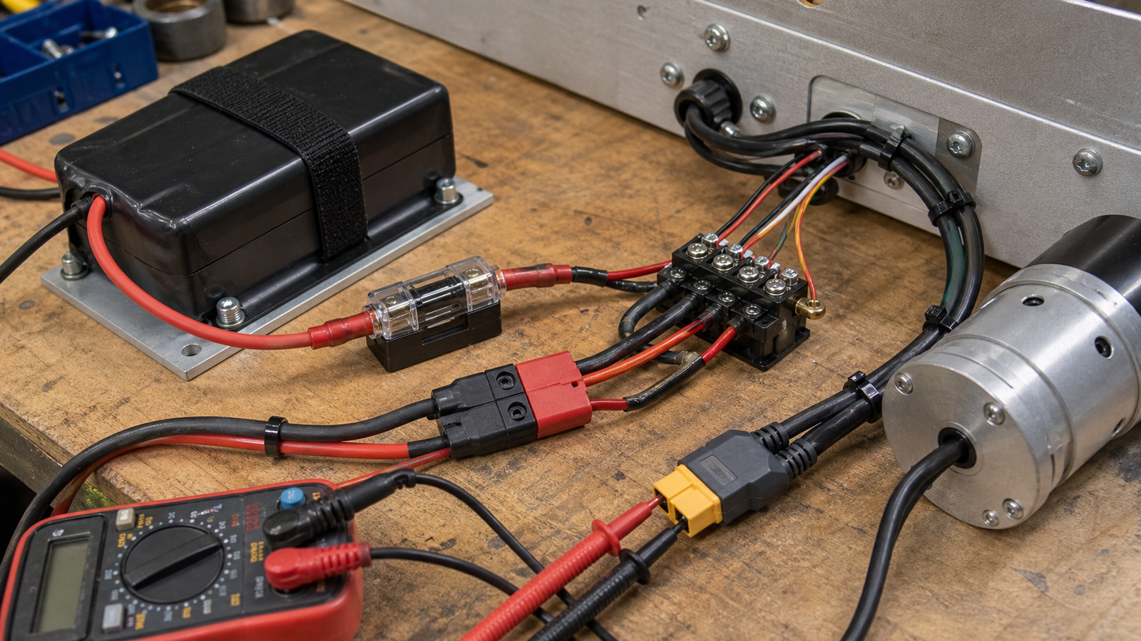
Connector choice should start with the expected current, not the connector drawer. Anderson Power publishes resources for Powerpole connectors, a common family in robotics and amateur radio power distribution. FIRST’s WPILib documentation also gives students a useful model of robot wiring discipline: main breaker, power distribution, motor controllers, control electronics and documented connections.
For small maker robots, the same thinking applies at a smaller scale. A JST connector may be fine for a sensor. It is usually not the answer for a motor battery path. A USB-C cable can deliver serious power under USB Power Delivery rules, but only when the source, sink, cable and negotiation all support the intended level. The USB-IF describes USB Power Delivery as an evolution from simple data charging into negotiated power delivery.
Voltage drop is a moving target
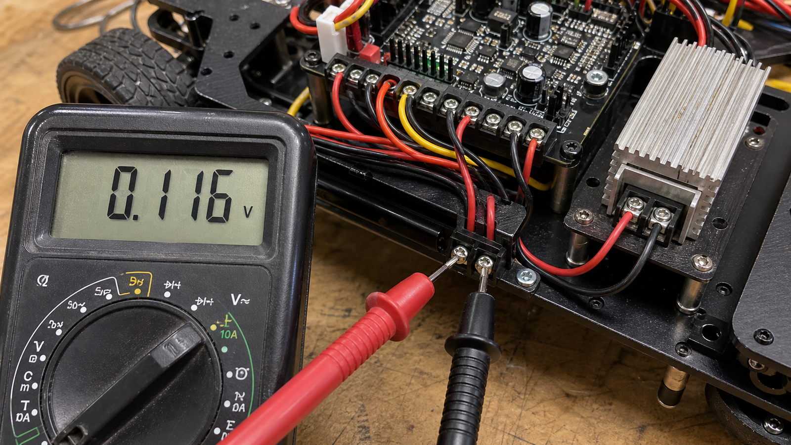
Voltage measured with no load can be misleading. A battery may show a healthy voltage until motors start, wires warm up or a connector with poor contact adds resistance. The result can be a momentary brownout: the robot still has power, but the controller or radio sees a dip deep enough to reset.
A better test is to measure at the controller while the robot runs a realistic load. Compare battery voltage to controller input voltage during acceleration, turning, lifting or camera startup. If the difference grows under load, inspect wire length, gauge, connector condition, crimp quality and distribution points.
TVG’s recent I2C sensor wiring guide made a similar point for signal wiring: intermittent faults often appear only when the robot moves. Power wiring has the same problem, but the consequences can reset the whole system.
Fuse placement and service loops
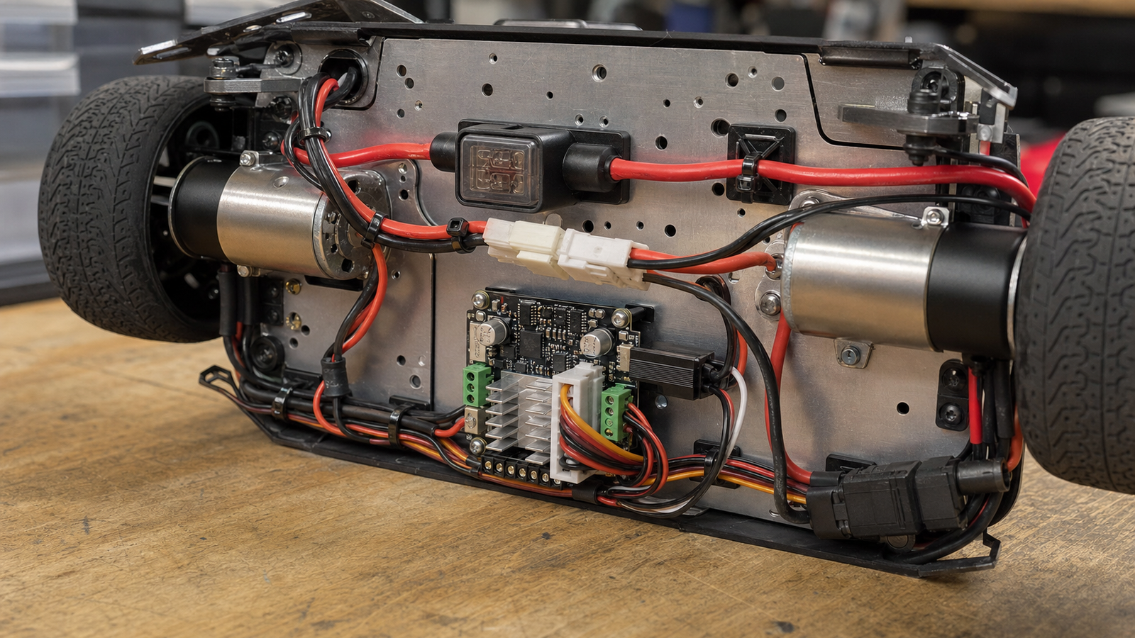
Fusing belongs close enough to the source to protect the wiring path, not only the device at the far end. If a battery lead shorts against a chassis, the fuse should open before the wire becomes the fuse. Labs should also avoid burying fuses where students cannot inspect or replace them safely.
Service loops and strain relief are easy to dismiss until the robot vibrates, flips or gets carried by a cable. A cable should not pull directly on a solder joint, board connector or motor-controller terminal. Add mechanical support before the electrical joint, especially near batteries and moving assemblies.
A practical pre-test checklist
- Identify the main current path from battery to distribution.
- Confirm connector current ratings and polarity discipline.
- Check wire gauge and length against expected load.
- Verify the fuse or breaker is appropriate for the wiring.
- Measure controller voltage while motors are loaded.
- Inspect crimps, solder joints and screw terminals after motion.
- Label removable leads by function, not just color.
TVG Take
For maker labs, the best wiring upgrade is often not a premium connector. It is a repeatable power test: loaded voltage measurement, tug check, fuse check and routing review before the robot leaves the bench. Good wiring makes software debugging more honest because the controller stays alive long enough for the real bug to appear.