Editorial mode: Analysis / Guide. USB-C Power Delivery is now common enough that maker labs treat it like a universal power answer. That is useful, but risky. A USB-C plug does not tell students whether a supply can negotiate the voltage they need, whether a cable is rated for the current, whether a hub back-feeds power, or whether a single-board computer will throttle under load.
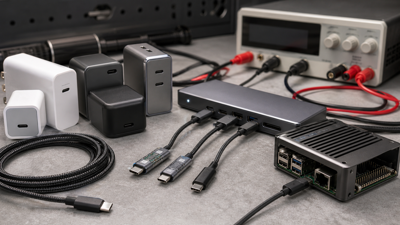
The USB-IF describes USB Power Delivery as a way for devices to negotiate higher power over USB-C. On a maker bench, that negotiation is the point: the charger, cable, hub, trigger board, battery bank and target device each have a role. Treating them as interchangeable is how labs end up with brownouts, random resets and hard-to-reproduce failures.
The quick answer
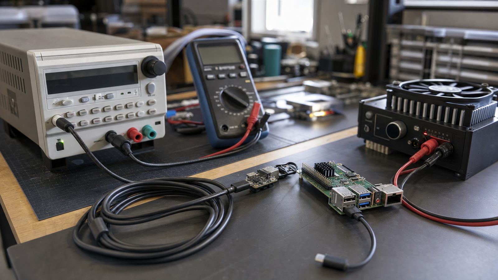
A reliable USB-C PD lab needs known-good chargers, marked cables, a load tester or PD meter, powered hubs for peripherals, and written rules for what can power motors, LEDs, heaters or battery chargers. USB-C is convenient for logic and compute. It is not automatically a safe motor bus or high-current experiment rail.
What to verify before plugging in
Start with the source. A charger that advertises 5 V, 9 V, 15 V and 20 V profiles behaves differently from a basic 5 V wall adapter. Battery banks may shut off when the load is too small, which can break microcontroller data loggers. Some supplies drop negotiated voltage after a fault and do not recover until the cable is reconnected.
Next, check the cable. USB-C cables are not all the same. Longer cables, charge-only cables and older unmarked cables can create voltage drop or missing data paths. For education spaces, the easiest fix is not a lecture; it is a small cable library with tested cables, colored tags and a retirement bin for mystery leads.
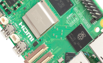
Then check the load. A Raspberry Pi, Jetson-class board, LED strip, servo rail and battery charger should not all be treated like the same sink. The Raspberry Pi documentation is sometimes blocked by automated fetchers, but the product line’s public guidance consistently emphasizes appropriate official power supplies and current capacity. For lab practice, measure the loaded system instead of relying only on the label on the adapter.
Bench process
Use a PD meter or trigger board only when students understand what it is doing. A trigger board that requests 20 V can be useful for a buck converter experiment, but it can also destroy a 5 V-only device if the wiring is careless. Keep trigger boards physically separate from everyday charging cables.
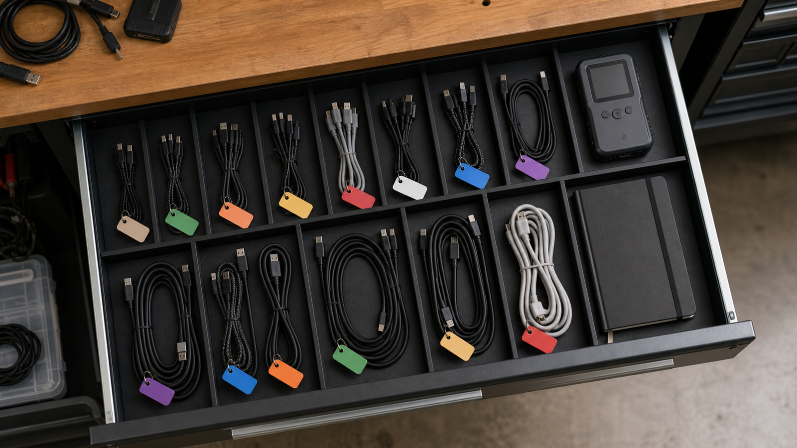
For field kits, write the power budget on the case. Include the expected voltage, maximum load, cable requirement, whether a hub is powered, and what must not be connected. That note is more valuable than a generic “USB-C” label because it follows the system into competitions, demos and classrooms.
TVG Take
USB-C PD is a good maker-lab standard when it is treated as a negotiated power system, not a magic connector. The practical win is fewer wall warts and cleaner field kits. The engineering risk is that invisible negotiation hides failure modes from beginners. Labs that test, tag and document their USB-C gear will get the benefit without turning every reset into a mystery.