
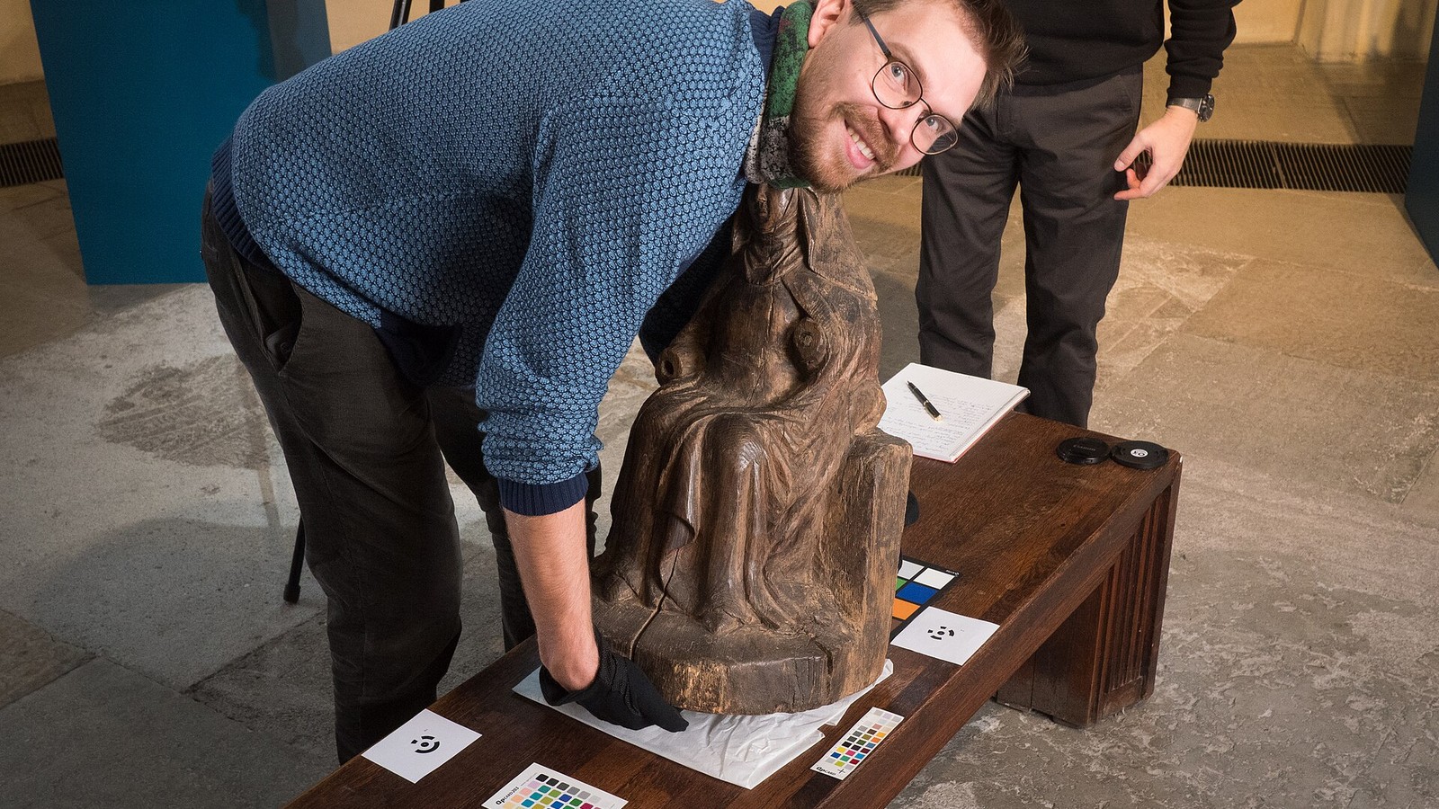
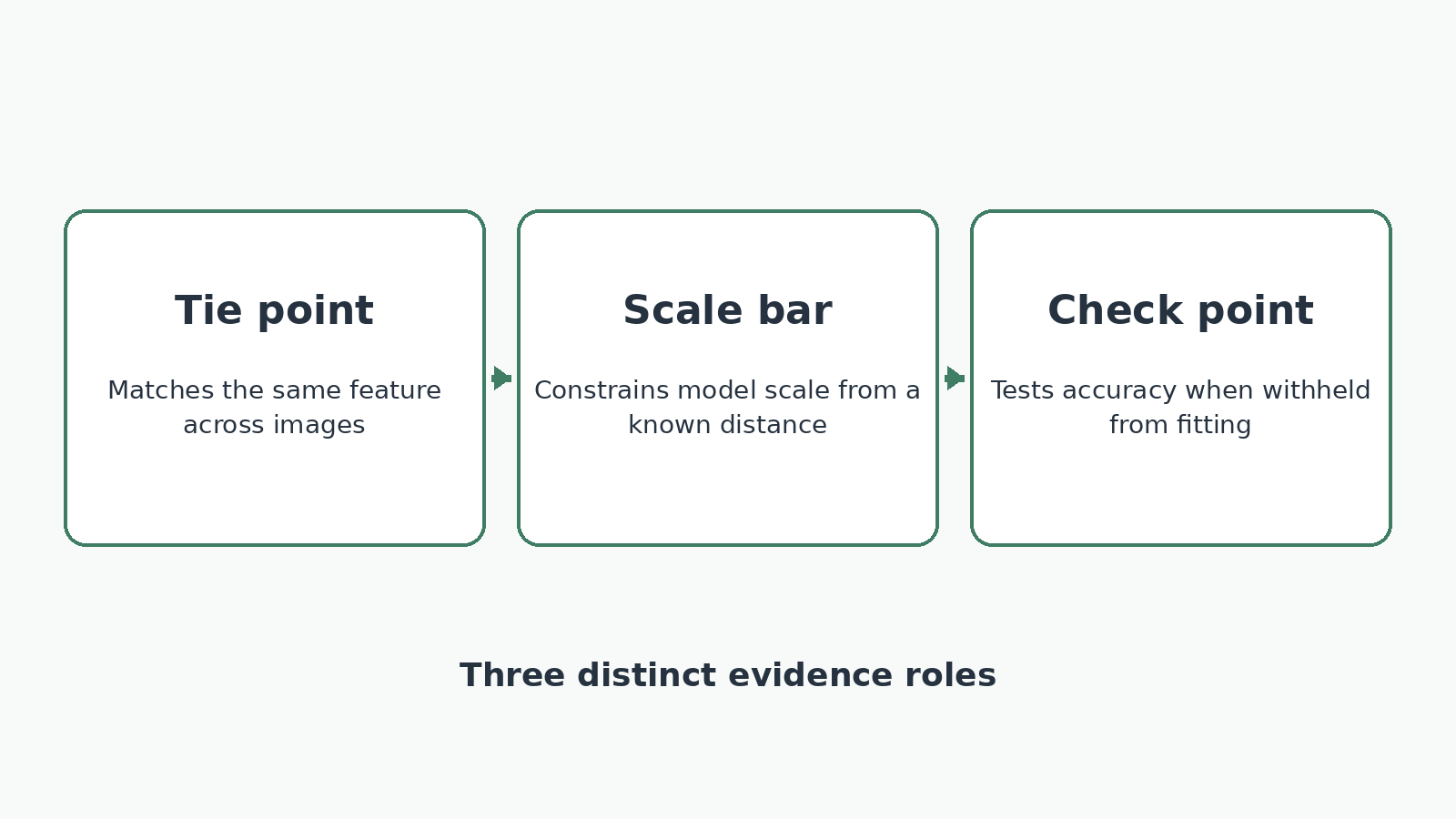
A photogrammetry model can align cleanly and still have the wrong scale—or report reassuring errors from points that helped fit the model. Use tie points to connect images, scale bars to constrain dimensions and separate check points to test the finished result. These are different evidence roles, not interchangeable markers.
Quick Answer
- Use tie points to link overlapping images.
- Use multiple measured scale bars to constrain scale and expose placement mistakes.
- Withhold check points from fitting so they can test accuracy independently.
Start by naming the measurement claim
If the goal is only a visually convincing model, relative geometry may be enough. If the model will supply a dimension, fit check or repeatable comparison, the capture needs a traceable scale reference. If the result will support a consequential engineering decision, it also needs evidence that did not participate in estimating the solution.
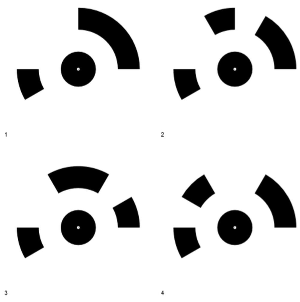
Agisoft’s Metashape documentation describes coded targets as printed markers that can serve as reference points for coordinate and scale definition or help alignment. Its scale-bar workflow links two marked points and assigns their known distance. RealityScan likewise describes control points as tools for camera-pose correction, georeferencing or model scaling.
Scale bars constrain; they do not validate themselves
One accurately measured distance can establish scale, but it cannot reveal every local deformation or a mistaken marker placement. Cultural Heritage Imaging’s scale-bar guidance, published through Agisoft, recommends more than one bar and explains that additional bars add checks and confidence. Put references across the volume of interest rather than clustering them in one easy corner.
A practical small-object setup uses rigid bars that remain in the same plane or volume as the object, are visible from several useful camera angles and are measured with an instrument appropriate to the claimed tolerance. Paper targets can be useful, but paper can curl, stretch or move. The recorded reference should identify the endpoints and the measured distance rather than relying on a nominal printed dimension.
A check point must stay out of the fit
Agisoft’s control-and-check-point guidance distinguishes points used to georeference the model from check points used to evaluate accuracy. The distinction disappears if the “check” point is enabled as control during adjustment. Withhold it, process the model, then compare its reconstructed position or distance with the independently measured reference.
Use check points where the decision matters: near both ends of a long object, across changes in depth, and away from the cluster of scale constraints. A low error beside the scale bar says little about an untested region on the opposite side. The ISPRS accuracy study on close-range UAV photogrammetry reinforces the broader principle that check-point error changes with control configuration and spatial distribution.
Do not move a check point into the fitted set simply to improve the report. If one region fails, investigate image coverage, blur, reflective surfaces, weak camera geometry or a moving reference. The failed check is useful evidence because it identifies where the model cannot support the intended measurement claim.
Read the residuals by role
Reprojection error helps diagnose image observations and alignment, but it is not a dimensional accuracy certificate. Scale-bar residuals show how well the model satisfies known distances that may have influenced the solution. Check-point residuals estimate performance at withheld locations. Report them separately, with units, placement and whether each reference was enabled during fitting.
Save the original images, target coordinates, measured distances, processing settings and residual report together. That record makes a later recapture or software comparison possible without pretending that one summary number describes the whole model.
This workflow does not turn consumer photogrammetry into metrology. It does make the evidence honest enough to identify whether a model is merely aligned, properly scaled or independently checked. Readers comparing capture methods can also use TVG’s phone LiDAR and handheld 3D scanner guide.

My experience with large terrain always required a manual adjustment for perspective distortion. I found that using a fixed grid system could sometimes introduce unintended errors.