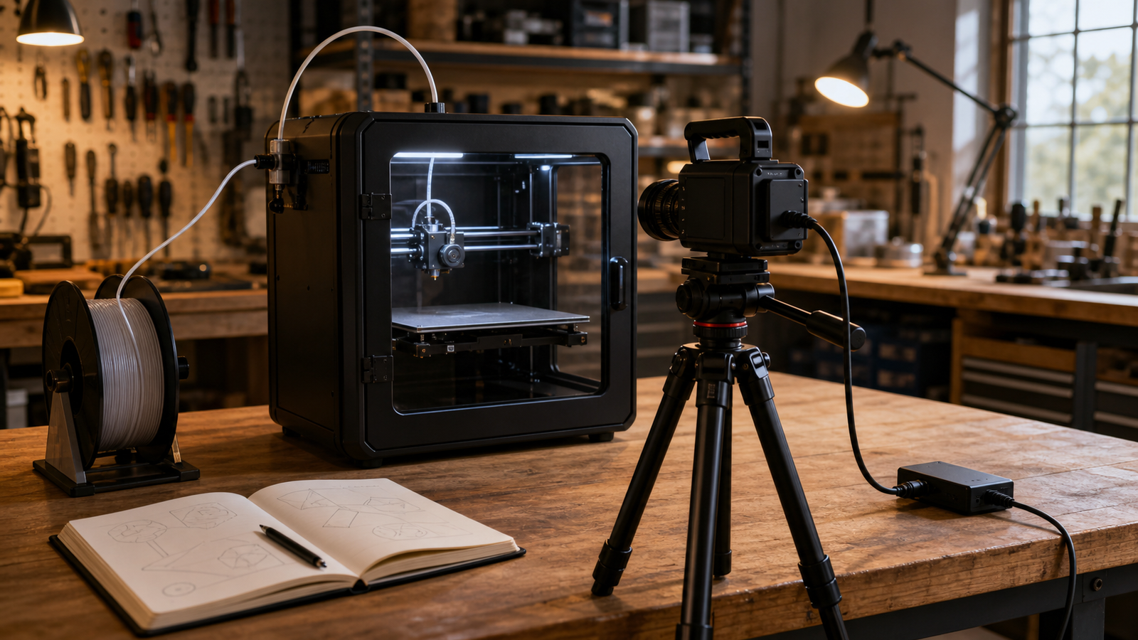
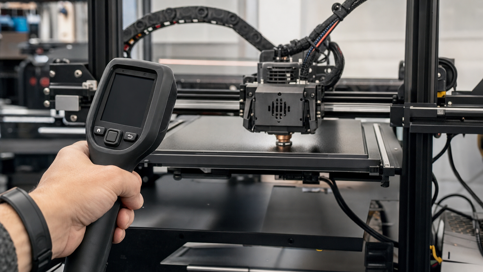
A thermal camera can make a 3D printer feel easier to understand. Bed heating patterns, enclosure gradients, hot-end behavior, stepper-driver areas, and cooling-air paths become visible in a way a normal photo cannot show. That makes thermal imaging a strong broadened-lane maker lab topic for TVG.
It also creates a trap. Thermal images are measurements, not magic truth. FLIR’s emissivity guidance explains why surfaces do not all report temperature the same way. Prusa’s documentation around thermal model protection shows how modern printers increasingly treat temperature behavior as part of reliability, not a simple display number.
Quick answer
Use a thermal camera for 3D printer troubleshooting by capturing baseline images, comparing the same scene under the same settings, checking emissivity and reflections, and logging printer state. Do not diagnose from one colorful image alone.
Where thermal imaging helps
Printer problems often look mechanical or slicer-related when heat is part of the story. A first layer may fail because the bed has a colder edge. An enclosure may trap heat around one axis. A part-cooling fan may change the local temperature more than expected. A wire or connector may deserve inspection because it appears warmer than nearby components under the same load.
Those observations are useful only when the setup is repeatable. The camera angle, distance, surface material, printer state, and ambient conditions all matter. A shiny metal part can reflect heat from something else. A black build surface and a reflective screw may look different even at similar temperatures.
Maker lab checklist
- Capture a baseline: record the printer when it is working normally before chasing failures.
- Use the same view: mark camera position and distance for repeat tests.
- Watch surface materials: emissivity and reflections can mislead students.
- Record printer state: nozzle temperature, bed temperature, fan speed, enclosure state, and print time matter.
- Compare, do not guess: look for changes across runs rather than one dramatic color patch.
- Inspect safely: power, moving axes, hot ends, and wiring should be handled with normal lab caution.
The same discipline appears in TVG’s USB-C field power checklist: a tool becomes useful when it is part of a repeatable diagnostic process.
What not to overclaim
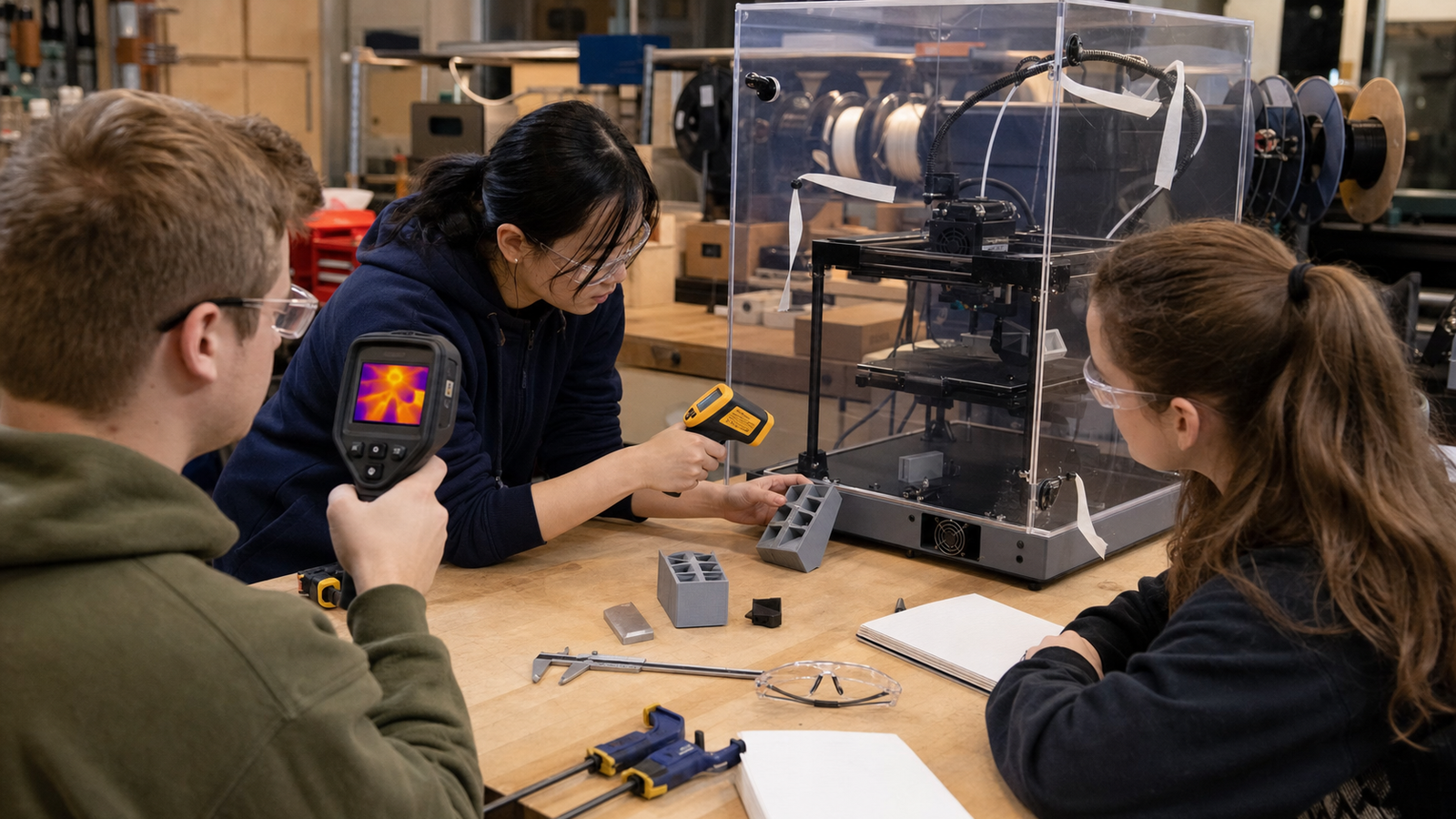
A maker lab should not use a low-cost thermal camera to certify electrical safety, prove a component is within specification, or replace manufacturer diagnostics. It is a discovery and comparison tool unless the measurement setup, calibration, surface assumptions, and instrument limits are understood. That distinction keeps the project honest.
The best classroom output is a short thermal log: normal warm-up, first-layer run, enclosure closed, enclosure open, fan change, and failure reproduction. Students can then compare images and notes instead of arguing over one color palette, and they can repeat the same setup after a hardware change to see whether the change actually helped.
TVG Take
Thermal cameras are excellent 3D printer teaching tools when the lab focuses on evidence. Baseline images, repeatable setup, surface awareness, and written logs turn a flashy camera into an engineering instrument. Without those habits, thermal imaging becomes just another colorful screenshot.