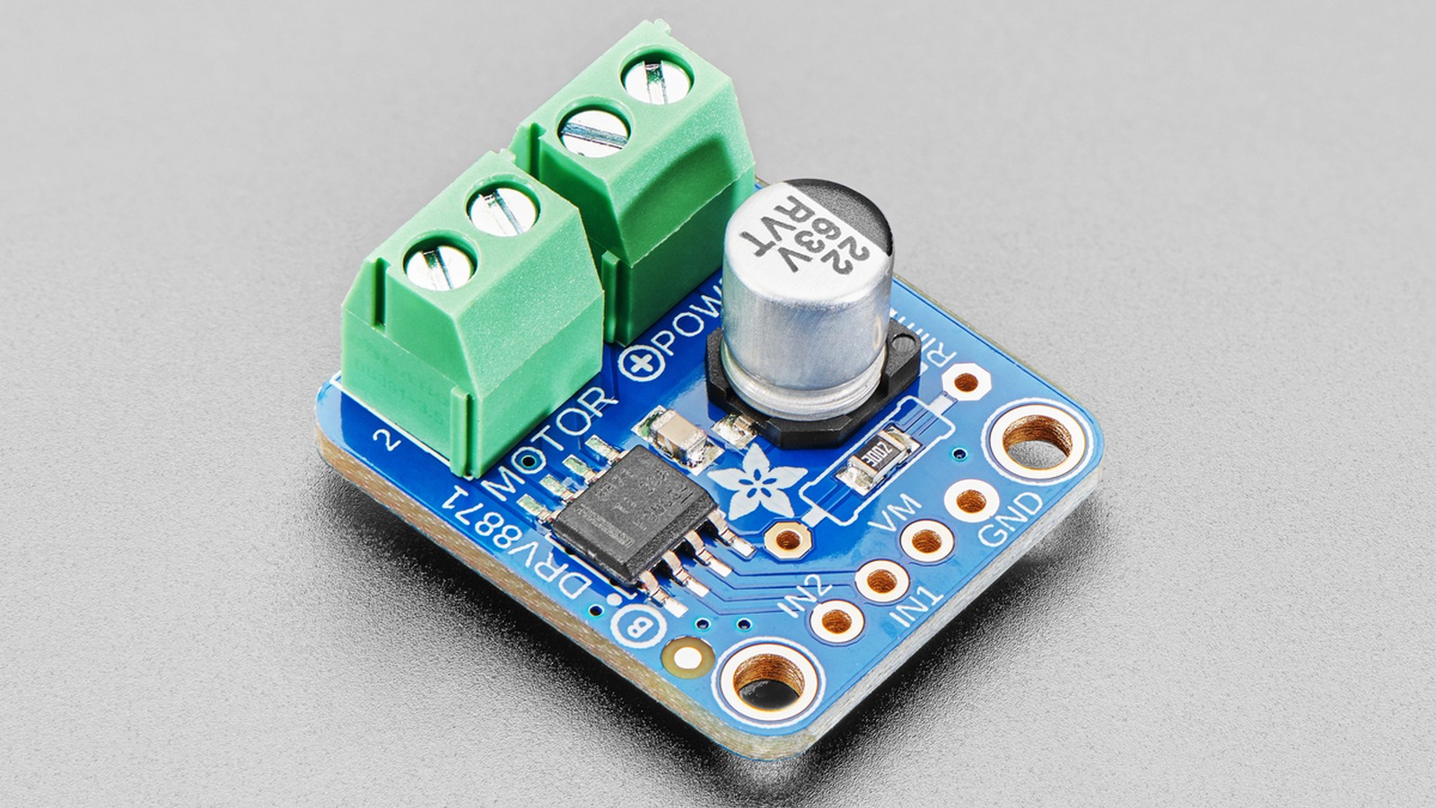
The DRV8871 does not use a low-value current-sense resistor in the motor path. It measures current internally and uses one resistor from ILIM to ground to set the chopping threshold. The nominal relationship in Texas Instruments’ datasheet is ITRIP = 64 kV / RILIM, with resistance entered in kilohms: 32 kΩ gives a nominal 2 A limit.
That threshold is a control point, not a guarantee that the motor, board or driver can carry the same current continuously. Resistor tolerance, the device’s 59 kV to 69 kV ILIM constant range and board thermals all widen the real result.
Choose RILIM from a current band, not one number
For a target of 2 A, the nominal calculation gives 32 kΩ. Using the datasheet’s ILIM constant limits, the same ideal resistor corresponds to 1.84 A at 59 kV and 2.16 A at 69 kV before adding resistor tolerance. If the load must never exceed a hard current, choose the resistor against the high-side constant and tolerance, then verify that the lower-side current still produces enough torque.
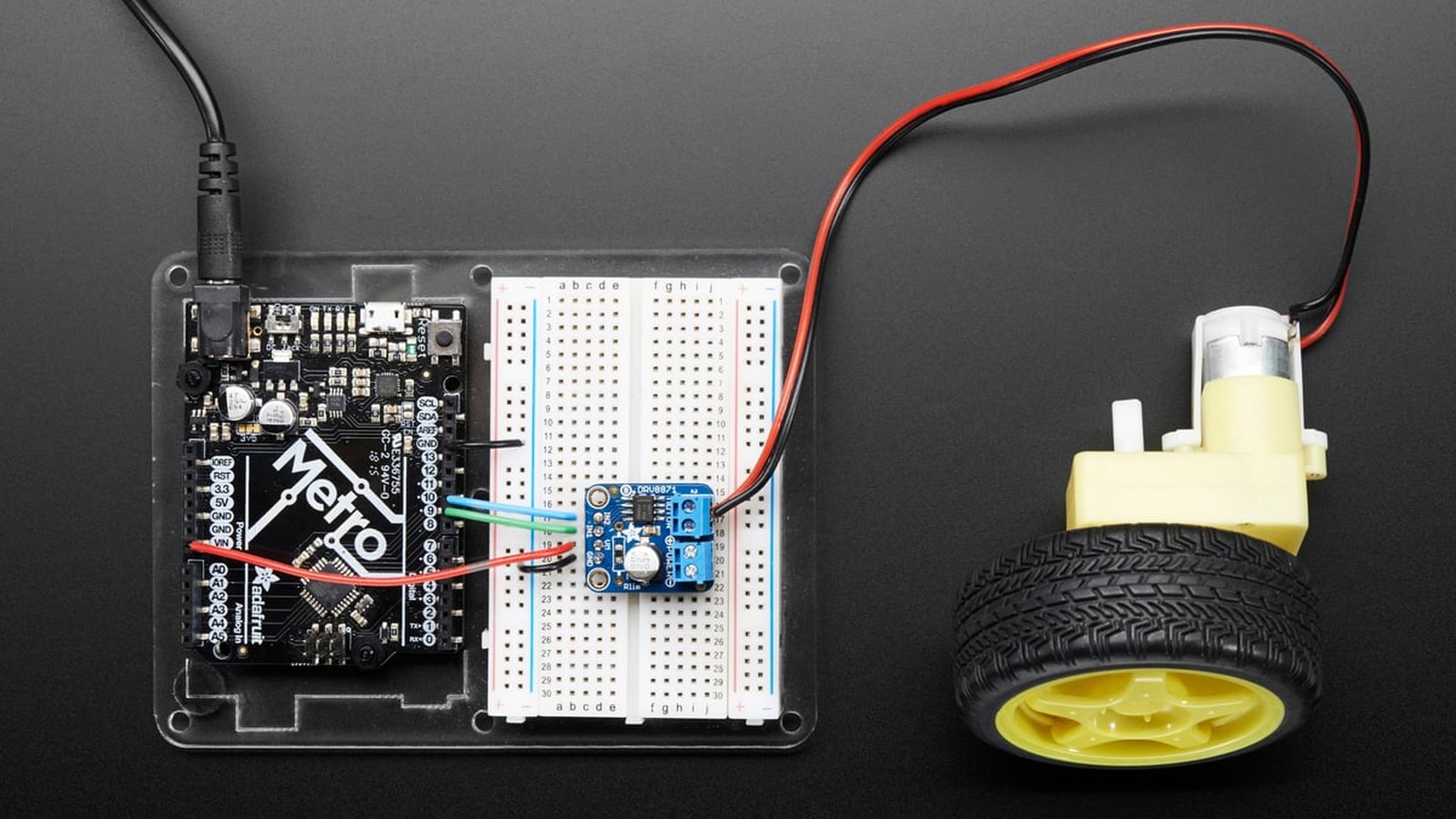
Texas Instruments specifies 15 kΩ as the minimum allowed RILIM. With the 64 kV nominal constant, that is about 4.27 A—already above the device’s 3.6 A peak output rating—so the published minimum is not an invitation to command that current in a real design.
Current regulation is a timed chop cycle
When motor current reaches ITRIP, the DRV8871 turns on both low-side FETs for slow decay. The typical off-time is 25 µs, after which the bridge follows the IN1 and IN2 inputs again. The time to the next trip event depends on supply voltage, motor back-EMF and winding inductance, so the current waveform changes with speed and load.
A current probe or small external measurement shunt used only for observation can show whether the bridge repeatedly enters regulation during startup. A multimeter average cannot resolve the 25 µs chop interval and may hide the difference between a brief startup limit and sustained thermal stress.
The 3.6 A figure is peak, not a continuous board rating
The datasheet rates the device for a 6.5 V to 45 V motor supply and up to 3.6 A peak output. It also lists a typical combined high-side plus low-side on-resistance of 565 mΩ. At 2 A, the simplified conduction estimate I²R is about 2.26 W inside the bridge while that current is flowing; switching and board conditions add more complexity.
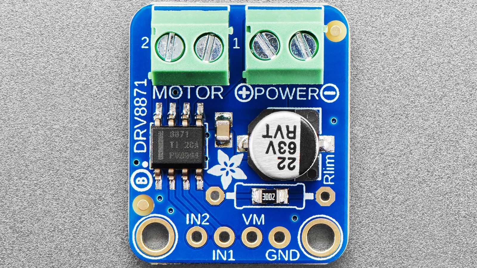
Continuous current therefore depends on copper area, airflow, ambient temperature, duty cycle and the package-to-board thermal path. A breakout can hit thermal shutdown even though the chosen RILIM is below the peak-current headline.
Separate current regulation from fault protection
Current regulation is normal operation: reaching ITRIP starts the slow-decay interval and then drive resumes. Overcurrent protection is a separate fault path for a short or much larger current event. The DRV8871 also includes undervoltage lockout and overtemperature protection; these protections can disable the bridge but do not replace correct current and thermal design.
The input truth table matters during recovery. Both inputs low select sleep and high impedance; one high and one low drives in a direction; both high apply brake. A controller that resets with both pins pulled low keeps the outputs off, while floating or incorrectly sequenced pins can create an unexpected state.
A practical setup sequence
- Use the motor’s expected loaded and stall current—not only its no-load current—to define a safe current band.
- Calculate RILIM from the 59 kV to 69 kV range and include resistor tolerance.
- Confirm the result does not rely on the 3.6 A peak figure as a continuous rating.
- Observe startup current and driver temperature under the actual supply, mechanical load and duty cycle.
- Distinguish repeated 25 µs regulation cycles from thermal, UVLO or overcurrent shutdown.
A correctly chosen resistor makes the DRV8871’s current regulation predictable. It cannot compensate for a motor that requires more continuous power than the package and board can dissipate.