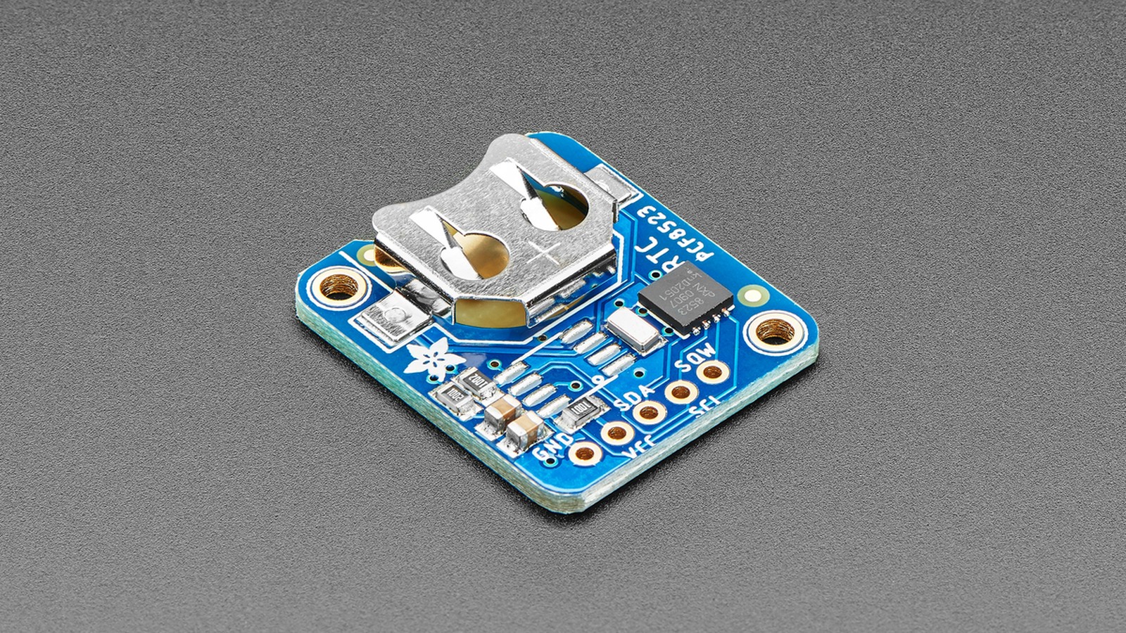
PCF8523 clock drift should be measured as elapsed-time error before changing the offset register. Record the RTC and a trusted reference at the start and end of a long interval, calculate parts per million as ppm = error_seconds / elapsed_seconds × 1,000,000, then apply the opposite correction sign. A clock that gains time needs a negative correction; a clock that loses time needs a positive one.
The PCF8523 offers two correction modes. Mode 0 changes the average rate by 4.34 ppm per least-significant bit and applies correction over a two-hour cycle. Mode 1 uses 4.069 ppm per LSB and applies correction every minute.
Convert measured error into a register step
Suppose an RTC gains 3.0 seconds over seven days. Seven days contain 604,800 seconds, so the measured error is about +4.96 ppm. In Mode 0, -4.96 / 4.34 = -1.14; the nearest available setting is -1 LSB, equivalent to -4.34 ppm. The remaining idealized error is about +0.62 ppm, or roughly 0.054 seconds per day.
The offset field is a signed seven-bit two’s-complement value with a range from +63 to -64. Mode 0 therefore spans +273.420 to -277.760 ppm; Mode 1 spans +256.347 to -260.416 ppm. Choose one mode, write the corresponding MODE bit and signed offset, then repeat the elapsed-time measurement rather than assuming the rounded value is exact.
Measure long enough to beat timestamp noise
One second of reading uncertainty equals 11.57 ppm over one day but only 1.65 ppm over seven days. Longer intervals make a one-second observation error less important. Read the RTC and reference as close together as possible and avoid comparing display screenshots captured at unknown phases of a second.
Temperature also matters because the 32.768 kHz tuning-fork crystal does not hold one rate over its full operating range. Calibrate near the temperature that dominates the application, or characterize multiple temperatures if the device moves between indoor, outdoor and enclosure-heated conditions.
Check the power path before calibrating the oscillator
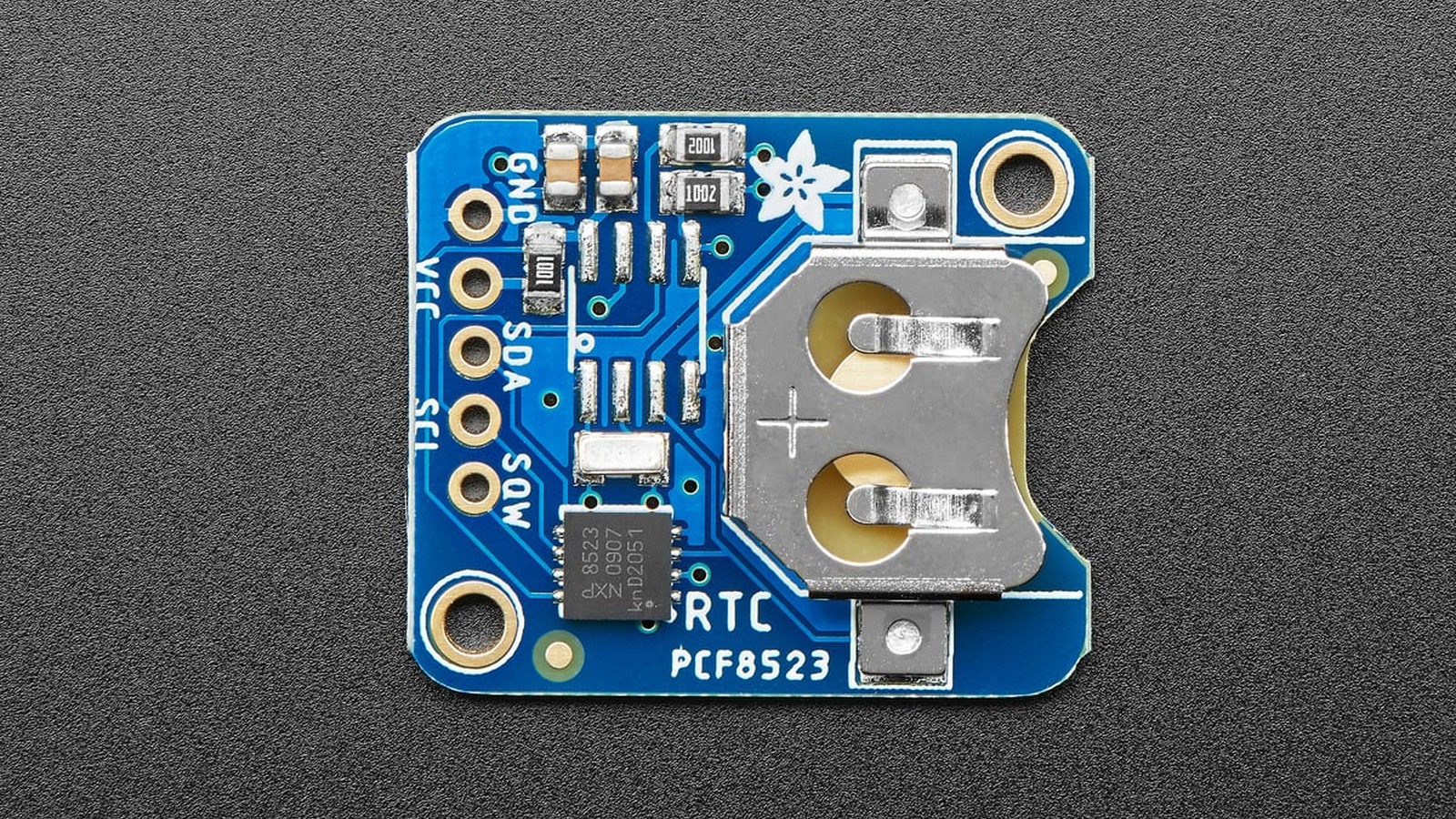
The PCF8523 can switch automatically from VDD to VBAT during a main-power failure. Its Control_3 register at address 02h contains the PM[2:0] power-management setting, the BSF battery-switch flag and the read-only BLF battery-low flag. A board with a dead or poorly seated coin cell can appear to have “drift” when it is actually losing time during outages.
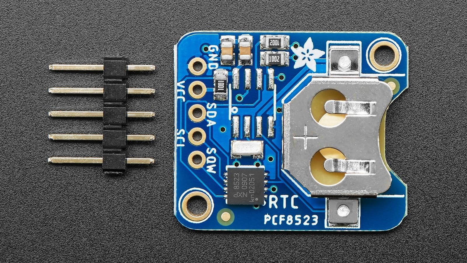
Verify that VBAT is present, that switch-over is enabled in the selected power-management mode and that BLF is clear. The datasheet specifies typical backup current of 150 nA at VDD = 3.0 V and 25 °C, but board leakage, battery self-discharge and temperature determine real service life.
Do not miss the oscillator-stop flag
The Seconds register at address 03h includes the OS oscillator-stop flag. If OS is set, the time value should be treated as suspect until software establishes a valid date and time and clears the condition according to the application flow. Applying an offset to an RTC that has stopped does not repair the underlying power, crystal or initialization fault.
The time and date counters use BCD. A driver must mask status bits before BCD conversion and should read the register block as one transaction. The PCF8523 freezes all counters when one RTC register is read, preventing an inconsistent result while seconds carry into minutes.
A disciplined calibration sequence
- Check OS, BLF and BSF and confirm the backup cell and power-management mode are sound.
- Set the RTC from a trusted reference and record both timestamps.
- Leave the system in a representative temperature and power environment for several days.
- Calculate signed ppm from the elapsed-time error.
- Divide by 4.34 ppm for Mode 0 or 4.069 ppm for Mode 1, round to the nearest supported signed step and apply the opposite sign.
- Repeat the same measurement interval and keep the before-and-after record.
This method separates oscillator-rate error from power failures and software mistakes. It also makes the limit of digital calibration visible: one register step is still several ppm, so the result cannot be finer than the selected mode’s resolution.