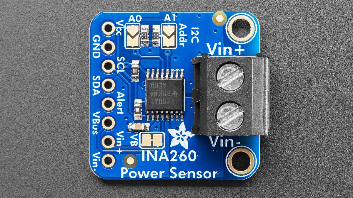
An INA260 alert can be electrically correct and still appear late when long ADC conversion times are combined with heavy averaging. The device evaluates measured results, so the response cannot be faster than the measurement window configured ahead of it.
Calculate that window before changing an overcurrent threshold. In continuous current-and-voltage mode, one averaged result includes both conversions: approximately N × (tCURRENT + tVOLTAGE), where N is the averaging count.
One sample may contain two conversions
The INA260 configuration register independently selects current and bus-voltage conversion times. Available settings range from 140 µs to 8.244 ms. In a mode that measures both quantities continuously, the device performs the current and voltage conversions in sequence rather than simultaneously.
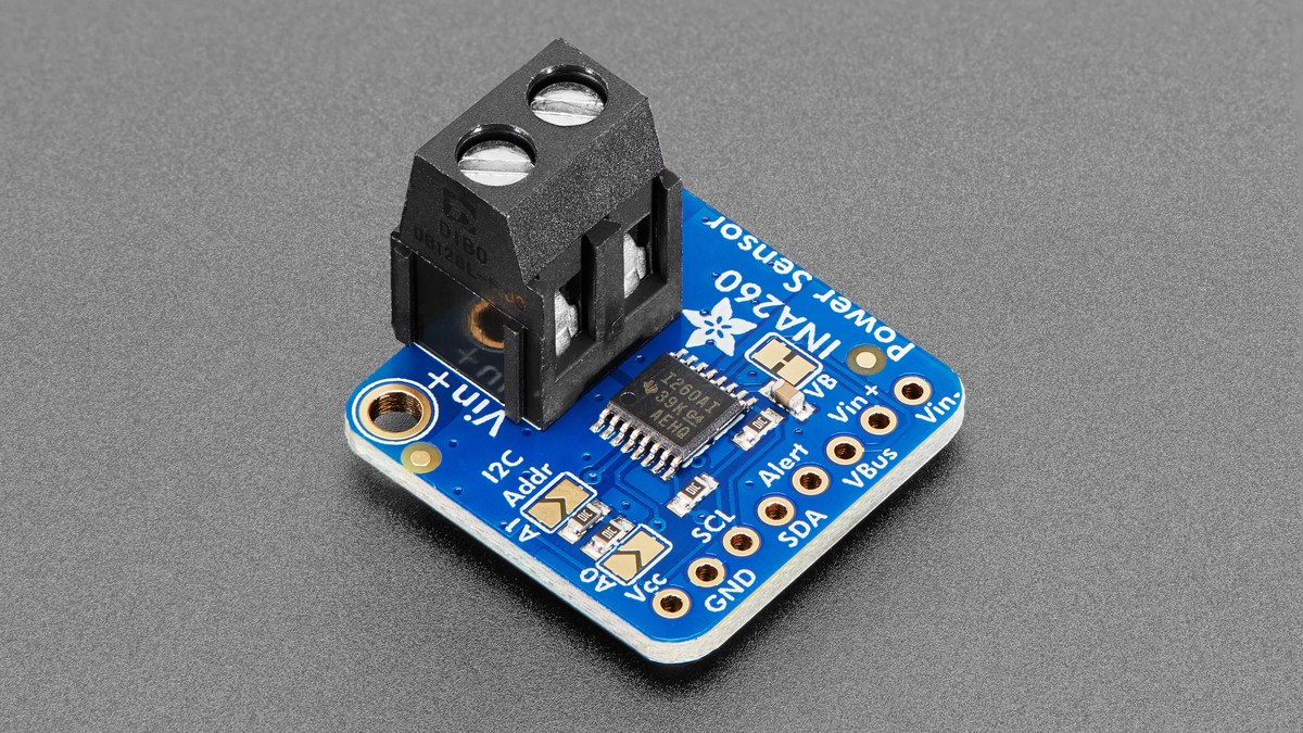
With both conversion times at 1.1 ms and averaging disabled, a complete current-plus-voltage cycle is about 2.2 ms. Select 64-sample averaging and the effective window becomes about 140.8 ms. At 1024 samples it becomes about 2.2528 seconds. Those figures are configuration latency, not an I2C polling problem.
Averaging trades response for stability
The averaging choices are 1, 4, 16, 64, 128, 256, 512 and 1024 samples. More samples can suppress short spikes and improve the stability of a displayed reading, but the same filtering can hide a brief overload from a limit based on the averaged result.
Choose the window from the event being protected. A motor startup pulse lasting tens of milliseconds needs different treatment from a sustained thermal overload. If the objective is fast current protection, a shorter current conversion and low averaging count preserve response; slower averaging can be reserved for a dashboard or energy estimate.
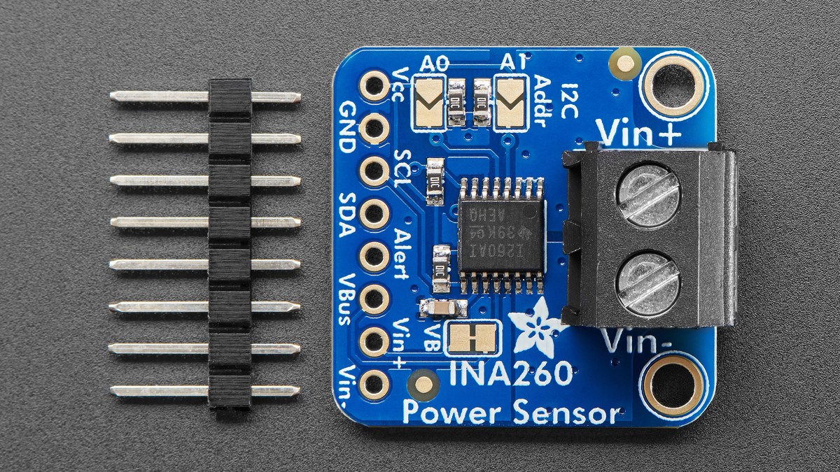
Threshold values use register LSB units
The INA260’s native ADC resolution is 16 bits. Texas Instruments defines a 1.25 mA current-register LSB, 1.25 mV bus-voltage LSB and 10 mW power-register LSB. An alert limit is encoded in the unit of the selected function, not in arbitrary engineering units.
For a 5 A overcurrent limit, the current threshold code is 5000 mA ÷ 1.25 mA = 4000, or 0x0FA0. For a 12 V bus-voltage limit, the code is 12000 mV ÷ 1.25 mV = 9600, or 0x2580. Endianness still matters when those 16-bit values are sent over I2C.
One pin monitors one selected limit function
The ALERT pin is open drain and can monitor overcurrent, undercurrent, bus overvoltage, bus undervoltage, overpower or conversion-ready state. The data sheet says only one limit function is monitored at a time; if software sets several limit-selection bits, the function in the highest significant bit position takes priority.
Transparent mode releases the alert when the fault clears. Latched mode holds it until the Mask/Enable register is read or the device is reset, depending on the documented sequence. A latched configuration can therefore look like a timing failure if firmware only watches the GPIO and never performs the clearing read.
Debug in order: verify the pull-up and polarity, read back the configuration and selected function, calculate the conversion-and-averaging window, encode the threshold in the correct LSB units, then observe both the register value and ALERT state over more than one full window. That separates intentional digital filtering from a genuinely incorrect limit or latch setting.