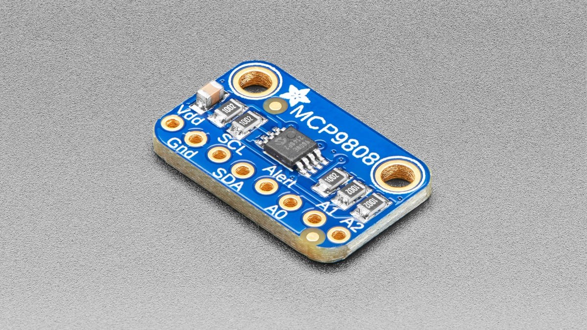
An MCP9808 alert that never rises, chatters near a limit or reacts later than expected can come from three different layers: the open-drain output wiring, the selected comparator or interrupt behavior, and the sensor’s conversion timing. Changing the threshold alone does not separate them.
Start by proving the pin has a pull-up and that firmware reads temperature normally. Then confirm alert polarity and mode, add enough hysteresis for the thermal noise around the boundary, and choose a resolution whose conversion time matches the required response.
ALERT needs an external pull-up
Microchip specifies ALERT as an open-drain output. It can pull the line low, but it cannot drive the line high; the circuit needs an external pull-up to the controller’s valid logic voltage. A floating input can look intermittent, while a pull-up to an incompatible rail can violate the host GPIO limit even though the sensor itself accepts a 2.7 V to 5.5 V supply.
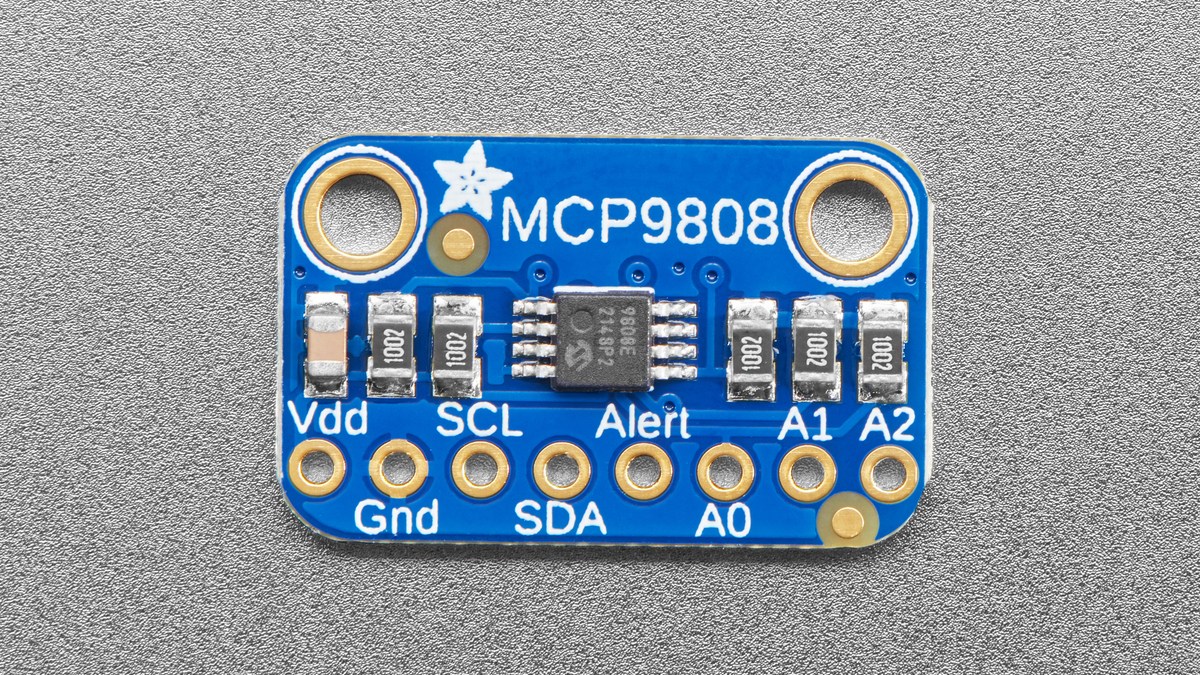
The configuration register controls active-high or active-low polarity. Check the actual idle level with the threshold safely away from ambient temperature, then move one limit across the current reading. That simple transition distinguishes electrical inversion from a limit that was encoded incorrectly.
Comparator and interrupt modes clear differently
In comparator mode, the output tracks the programmed boundary behavior and deasserts when temperature returns through the applicable limit plus hysteresis. In interrupt mode, the alert latches and must be cleared through the sensor’s defined interrupt-clear behavior. Firmware that expects a continuously tracking comparator can therefore interpret a correctly latched interrupt as a stuck signal.
The MCP9808 provides lower, upper and critical temperature registers. Window behavior is useful when both too-cold and too-hot conditions matter, but a single GPIO still reports the configured event state; software should read the ambient-temperature and status bits before deciding which boundary was crossed.
Hysteresis must exceed boundary noise
The configuration register offers 0°C, 1.5°C, 3°C and 6°C hysteresis. With no hysteresis, a real temperature that wanders by a fraction of a degree around a threshold can repeatedly assert and clear comparator output. A larger setting creates a wider return boundary, reducing chatter at the cost of delaying the clear point.
Choose hysteresis from the process, not from the sensor’s smallest output step. The MCP9808 can report 0.0625°C increments, but Microchip’s maximum accuracy is ±0.5°C from −20°C to +100°C and ±1°C across −40°C to +125°C. Fine digital resolution does not make a noisy enclosure, unstable airflow or self-heating disappear.
Resolution also sets response latency
The four resolution settings change both the output step and the typical conversion time: 0.5°C takes 30 ms, 0.25°C takes 65 ms, 0.125°C takes 130 ms and 0.0625°C takes 250 ms. At maximum resolution, a control loop polling every 20 ms will mostly reread the same completed conversion.
If the alert appears slow, log the raw temperature and pin state with timestamps longer than one full conversion period. Reducing resolution can improve response when the application does not need the finest step. Increasing poll frequency cannot force the converter to produce fresh data faster.
The reliable sequence is electrical first, state behavior second and timing third. Once those are fixed, threshold and hysteresis values become meaningful rather than compensating for a wiring or mode mismatch.