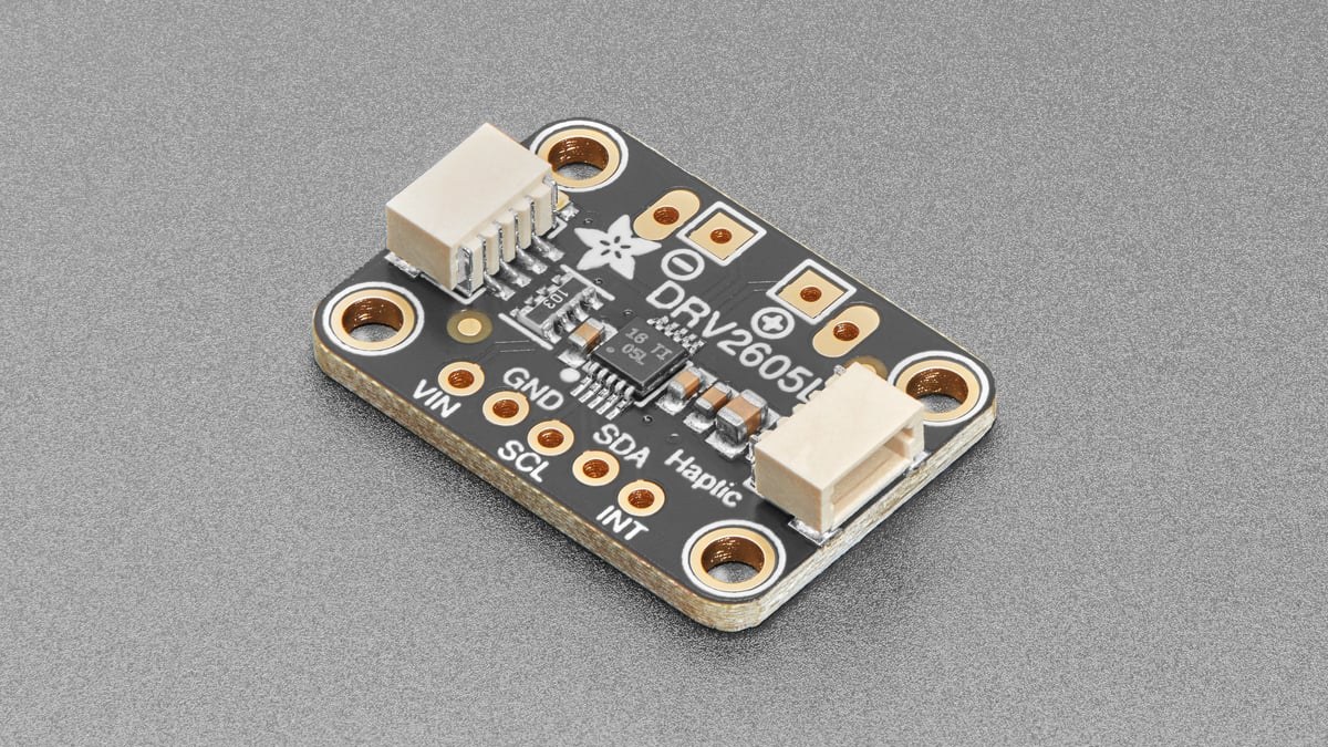
A DRV2605L that acknowledges on I2C but produces no vibration can still be in the wrong operating mode, hold an empty waveform sequence, miss the GO command or fail actuator calibration. Treat bus access as the first checkpoint, not the diagnosis.
The shortest path is to verify power and standby state, confirm ERM or LRA selection, load one known waveform followed by a zero terminator, assert GO and observe whether GO clears. If playback still fails, run diagnostics and read the status result before adjusting drive values.
Prove the command path with one effect
The DRV2605L waveform sequencer has eight slots in registers 0x04 through 0x0B. Playback starts when firmware sets GO in register 0x0C and stops at the first zero identifier or after all eight slots. For a basic check, place one valid library effect in slot 0 and zero in slot 1. Adafruit’s CircuitPython example uses effect ID 1 for “Strong Click – 100%.”
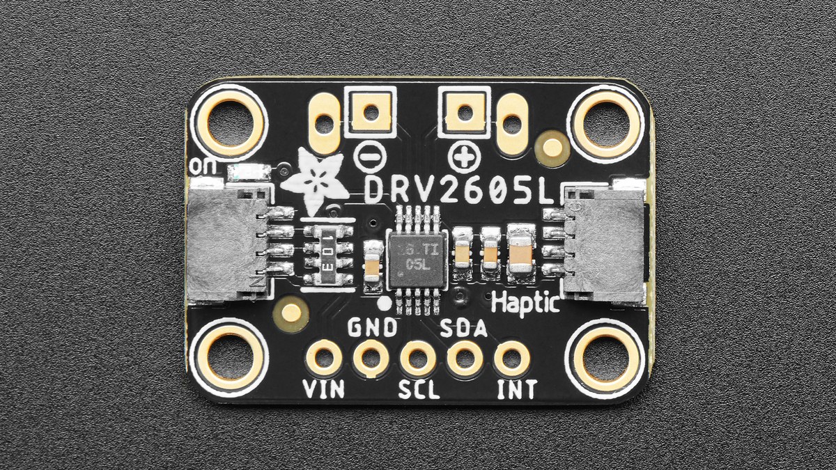
Read GO after triggering. It should return to zero when the process completes. A bit that never sets points toward a write, mode or standby problem. A bit that stays high suggests the selected process is not completing. A normal GO transition with no physical response moves attention to actuator selection, output wiring and diagnostic status.
Match firmware mode to the physical actuator
An eccentric rotating mass motor and a linear resonant actuator are not interchangeable configuration choices. Adafruit’s library defaults to ERM; its CircuitPython API uses use_LRM() for an LRA and use_ERM() to return to the ERM setting. A flat pancake vibration motor is commonly an ERM, but the actuator’s own part data should decide the mode.
For an LRA, the controller normally tracks resonance automatically unless LRA_OPEN_LOOP in register 0x1D is set. In open-loop PWM operation, the data sheet says drive frequency is the PWM frequency divided by 128. A wrong actuator mode can therefore leave the output poorly matched even though register writes succeed.
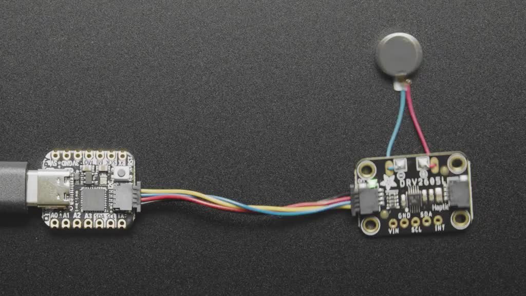
Use DIAG_RESULT instead of guessing at calibration
Status register 0x00 contains DIAG_RESULT. Texas Instruments says the bit is asserted when automatic level calibration fails, and the diagnostic process can also identify an absent, open or shorted actuator. That makes the status bit the next branch after a valid trigger sequence, not an optional detail.
Check the motor connection at the board and at the actuator, then confirm the rated-voltage and overdrive-clamp values suit the exact actuator. Closed-loop overdrive can exceed rated voltage during acceleration and braking, but the programmed clamp limits that output. Copying values from a different motor can cause weak behavior or failed calibration.
Keep trigger behavior unambiguous
I2C trigger mode starts a waveform by setting GO and cancels it by clearing GO. In edge-trigger mode, the IN/TRIG input needs a low-to-high pulse of at least 1 µs; another rising edge while GO is high cancels the transaction. In level-trigger mode, the pin must remain high for the waveform duration, and a falling edge cancels playback.
That difference explains why a brief GPIO pulse can work in one mode and stop an effect in another. Reduce the system to one documented trigger path until the motor responds, then add sequences or external triggering. This preserves the distinction between a host-command fault and a drive-stage or actuator fault.