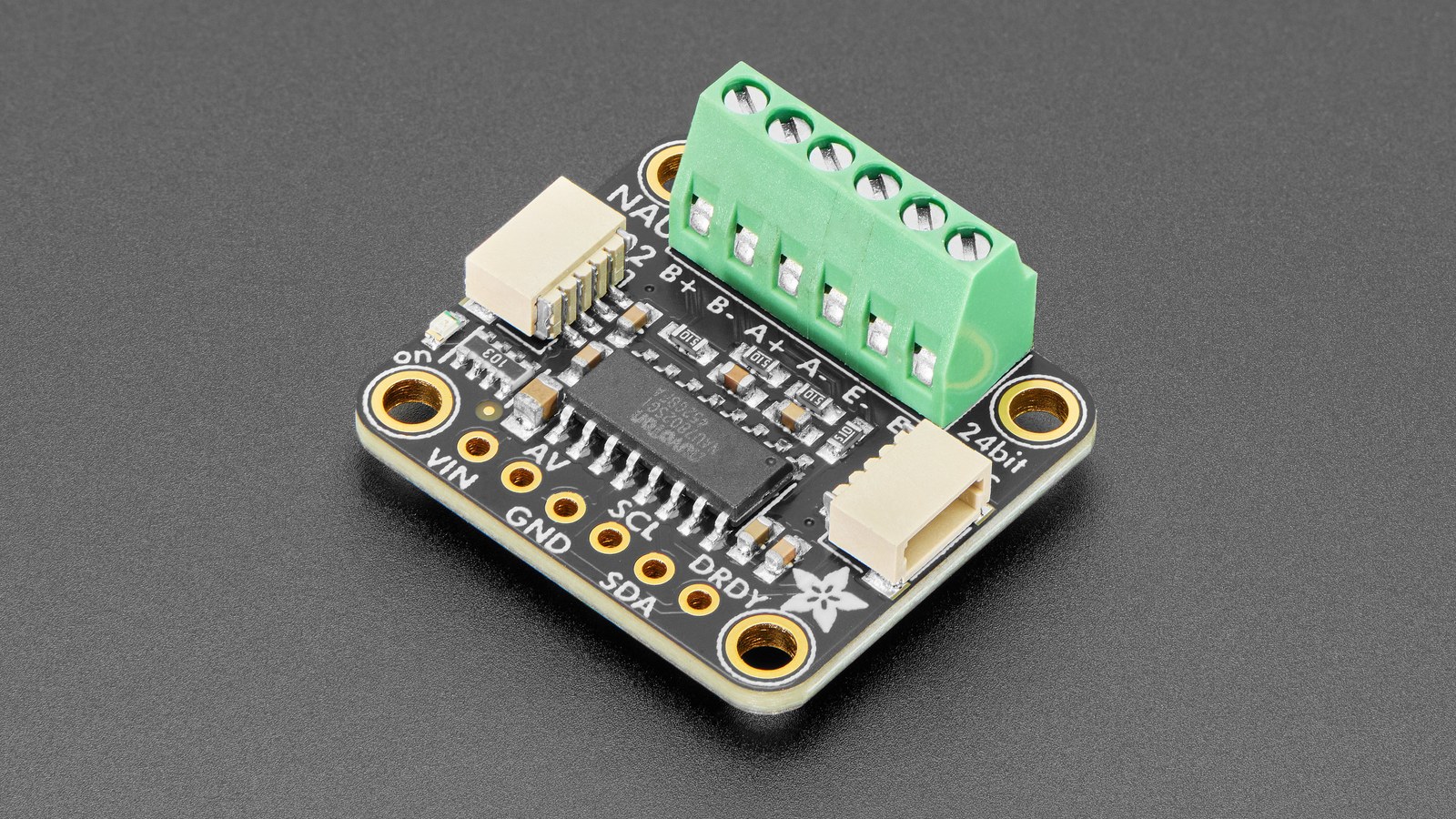
An NAU7802 can return 24-bit numbers before it is ready to return trustworthy load-cell measurements. Gain, output rate and calibration affect the converter together, and the chip exposes status bits that must be checked before firmware accepts a reading.
The reliable order is to power the analog blocks, choose the channel, gain and conversion rate, run the appropriate ADC calibration, wait for completion, check the error flag, and only then perform tare and known-mass calibration for the assembled scale.
Choose gain from bridge signal and reference voltage
The NAU7802 Rev. 2.6 data sheet specifies programmable gain from 1 to 128. Its differential full-scale input is ±0.5 × (VREF/PGA). At gain 128, only a small differential bridge signal fits before clipping; at lower gain, the input range grows but fewer converter codes represent the same load-cell change.
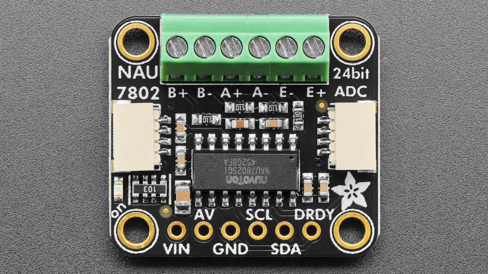
Start from the load cell’s sensitivity and excitation voltage, then estimate the maximum differential output. Leave headroom for overload, bridge imbalance and temperature shift. A clipped sample cannot be repaired by averaging or by changing the scale factor afterward.
Sample rate sets a noise and response trade-off
The converter’s programmable output rates include 10 and 80 samples per second. Nuvoton specifies 50 nV RMS noise at 10 SPS and gain 128, compared with 150 nV at 80 SPS and the same gain. The corresponding −3 dB bandwidth figures are 2.27 Hz and 18.17 Hz. The slower setting favors stable weighing; the faster setting follows changes sooner but passes more noise.
Averaging 80-SPS readings is not automatically equivalent to the 10-SPS filter response. The on-chip sigma-delta path and FIR filter determine rejection and bandwidth before software sees a sample. Select the rate for the motion you need to observe, then design any additional filtering around that rate.
Wait for calibration and check the error bit
Calibration starts by setting CALS at register 0x02 bit 2. CALS remains 1 while calibration is active and returns to 0 when the cycle completes. Firmware must then inspect CAL_ERR at register 0x02 bit 3; a clear completion bit alone does not prove success.
Nuvoton recommends calibration after initial power-up, a long power-down, PGA gain changes, supply changes, significant temperature changes and channel changes. That list matters because calibration coefficients compensate converter and PGA conditions that may no longer match after reconfiguration.
ADC trim is not scale calibration
Internal calibration removes internal PGA gain and offset errors. External ADC calibration can include errors at the input pins. Neither step knows the mechanics of the finished scale: load-cell mounting, preload, platform leverage and the conversion from counts to grams still require a system tare and one or more known loads.
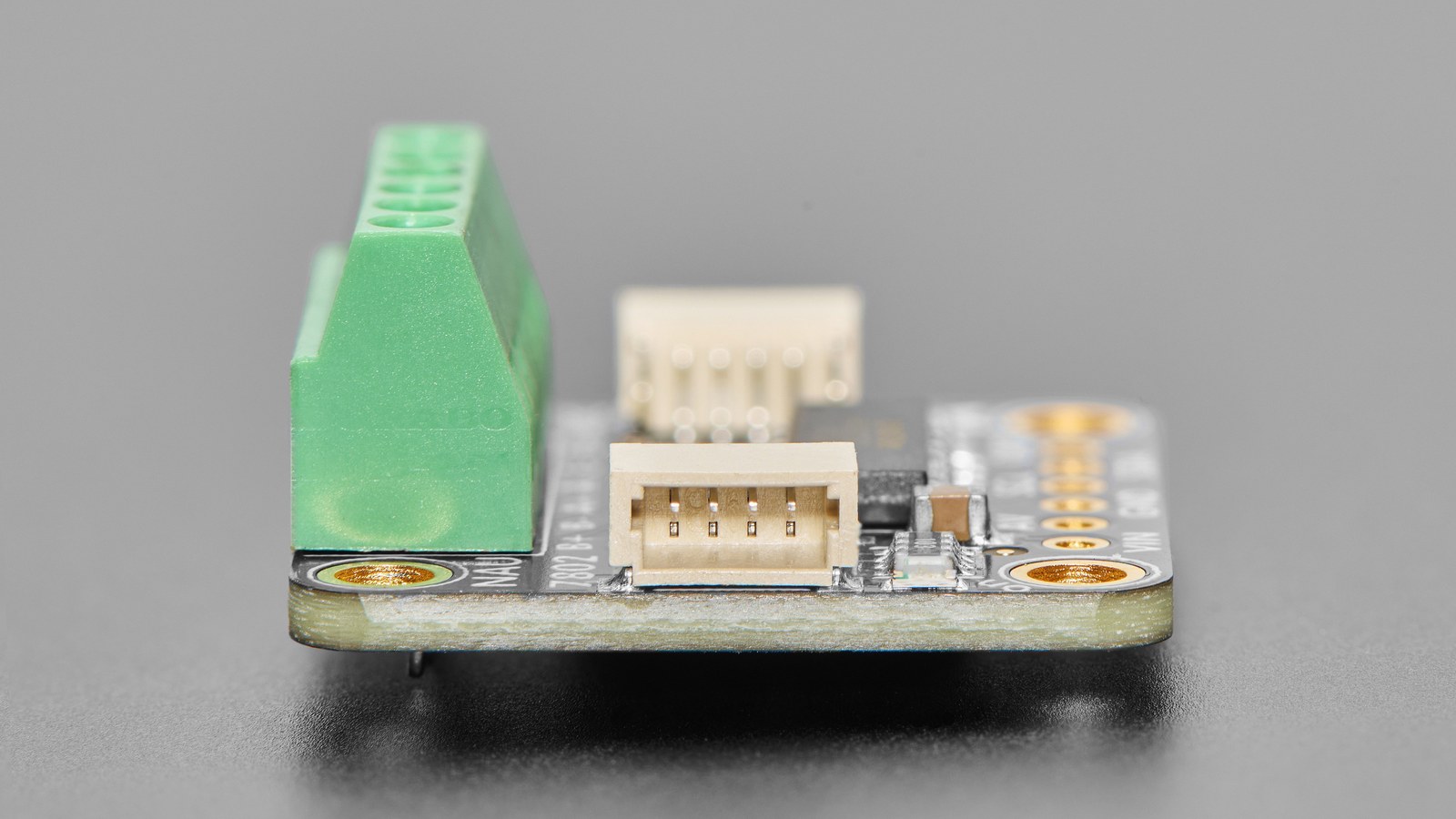
The Adafruit breakout exposes the NAU7802 at fixed I2C address 0x2A. Multiple breakouts on one bus therefore require an I2C multiplexer rather than address straps. The board is intended for four-wire Wheatstone-bridge sensors and provides Arduino and CircuitPython/Python software paths.
Keep the two calibration layers explicit in code and logs. Store the selected gain and rate alongside the system scale factor, and invalidate that factor when mechanics or excitation conditions change. The same measurement discipline applies to HX711 scale calibration: stable electronics do not cancel mechanical creep, off-center loading or temperature drift.